AC Theory
In today’s advanced AC Power applications, improvements in measurement and understanding complex current and voltage have become more crucial.
This guide provides an overview of the fundamental AC theory parameters and its significance.
Learning the basic concepts of RMS values, average values, real and apparent power, power factor, crest factor, harmonic distortion and measurement techniques will allow you to better understand the fundamental AC Theory.
UPDATED AUG 29 2024
1. RMS (Root Mean Squared Value)
The RMS value is the most commonly used and useful means of specifying the value of both AC voltage and current.
The RMS value of an AC waveform is that which when applied to a given circuit for a given time, produces the same expenditure of energy when a DC source is applied to the same circuit for the same interval of time.
The RMS value is essential for evaluating the power available from an AC source and a critical measure for quantifying AC voltage & current.
CALCULATION:
The calculation of an RMS value can best be described by considering an AC current waveform and its associated heating affect such as that shown in fig.1(a) below:
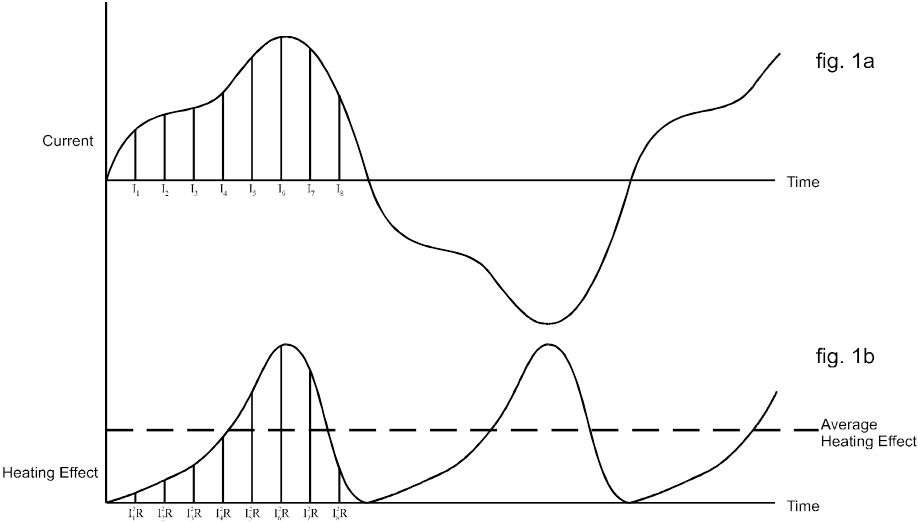
If this current is considered to be flowing through a resistance the heating effect at any instant is given by the equation:
![]()
By dividing the current cycle into equally spaced coordinates the variation of the heating effect with time can be determined as shown in fig. 1b.
The average heating effect (power) is given by:
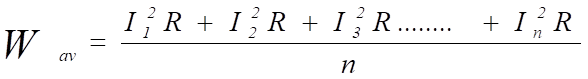
If we wanted to find the equivalent value of current that would produce the average heating effect value shown above then the following applies:
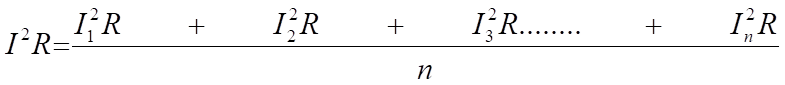
therefore
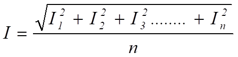
= the square root of the mean of the squares of the current
= the RMS value of the current.
This value is often termed the effective value of the AC waveform as it is equivalent to the direct current that produces the same heating effect (power) in the resistive load.
For a pure sinusoidal waveform:
RMS = Peak Value / SQRT (2)
= Peak Value x 0.707
2. Average Value
The average value of a sinusoidal wave is the mean of all the instantaneous values of one-half cycle as the average value over a full cycle is zero for symmetrical waveforms like the AC waveform.
The average value of a waveform such as that shown in fig. 2 is given by:
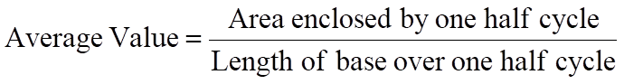
It is clear the average value can only have real meaning over one half cycle of the waveform as for a symmetrical waveform the mean or average value over a complete cycle is zero.
Most simple multimeters determine AC values by full wave rectification of the AC waveform followed by a calculation of the mean value.
Such meters however will be calibrated in RMS and will make use of the known relationship between RMS and average for a sinusoidal waveform
i.e.: RMS = 1.11 x mean.
However, for waveforms other than a pure sine wave the readings from such meters will be invalid.
3. Real and Apparent Power (W & VA)
Real Power is the actual amount of power being used or dissipated in a circuit while apparent power is the combination of both real power reactive power.
It is the product of a circuit’s voltage and current without reference to the phase angle.
Since apparent power has a direct relation to the RMS value (both were defined as the actual amount and effective value of AC current and AC voltage) the simple formula for the apparent power is S (apparent) = V(rms) x I (rms) and is measured in Volt-Amps (VA).
APPLICATION:
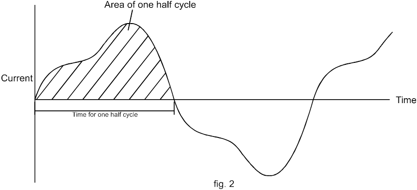
If a sinusoidal voltage source of say 100 V RMS is connected to a resistive load of say 100 Ohms, then the voltage and current can be depicted as in fig. 3a. and are said to be in phase.
The power that flows from the supply to the load at any instant is given by the value of the product of the voltage and the current at that instant , as illustrated in fig. 3b.
From this it can be seen that the power flowing into the load fluctuates (at twice the supply frequency) between 0 and 200 Watts and that the average power delivered to the load equals 100 Watts – which is what one might expect from 100 V RMS and a resistance of 100 Ohms.
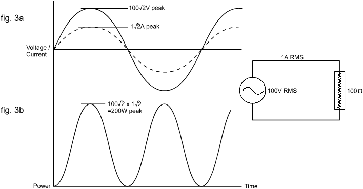
However, if the load is reactive (i.e. containing inductance or capacitance as well as resistance) with an impedance of 100ohms, then the current that flows will still be 1A RMS but will no longer be in phase with the voltage. This is shown in fig. 4a. for an inductive load with the current lagging by 60o.
Although the power flow continues to fluctuate at twice the supply frequency it now flows from the supply to the load during only a part of each half cycle – during the remaining part it actually flows from the load to the supply.
The average net flow into the load therefore , is much smaller than in the case of a resistive load, with only 50W of useful powering delivered into the inductive load.
In both of the above cases the RMS voltage was equal to 100V RMS and the current was 1A RMS .
The product of these two values is the apparent power delivered into the load and is measured in VA as follows:
Apparent Power = Volts RMS x Amps RMS
Simply knowing the RMS voltage and current is not sufficient to determine the real power.
To accurately assess power—such as for evaluating heat loss or efficiency—we need a true AC power meter.
This device calculates the product of instantaneous voltage and current values and then displays the average of this product.
4. Power factor
It is clear that, in comparison with DC systems, the transferred AC power is not simply the product of the voltage and current values.
The power factor is defined as the ratio of real power to apparent power.

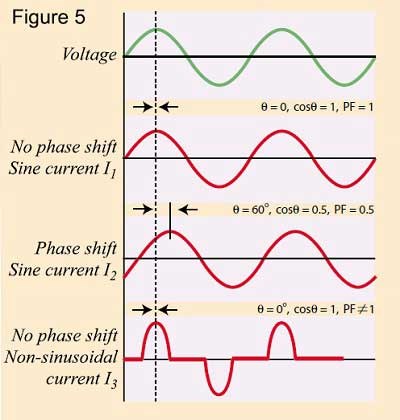
In the case of pure sinusoidal waveforms of AC current and voltage, Power factor depends on the phase of the angle in which it is measured.
Power factor will be unity (1) where voltage and current are in the same phase. (and Cos (0) = 1)
Lagging Power Factor is where the current lags the voltage by an acute angle.
Leading Power Factor is where the current leads the voltage by an acute angle.
Power factor will be zero where the voltage and current are out of phase by exactly 90 degrees. - this means that REAL power is also zero.
Importance: Power factor affects energy efficiency and load handling in AC systems.
CALCULATION:
In the previous example (real and apparent power) with an inductive load, the power factor is 0.5 because the useful power is exactly one half of the apparent power.
In the case of sinusoidal voltage and current waveforms the power factor is actually equal to the cosine of the phase angle between the voltage and current wave forms.
For example with the inductive load described earlier, the current lags the voltage by 60o, therefore:
![]()
It is for this reason that power factor is often referred to as cosθ.
It is, however, important to remember that this is only the case when both voltage and current are sinusoidal (Figure 5, I1 and I2 ) and that power factor is not equal to cosθ in any other case [Figure 5 (I3)].
This must be remembered when using a power factor meter that reads cosθ, as the reading will not be valid except for pure sinusoidal voltage and current waveforms.
A true power factor meter will compute the ratio of real to apparent power as described above.
5. Crest Factor
It has already been shown that for a sinusoidal waveform:
![]()
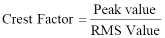
The relationship between peak and RMS is known as the Crest Factor and is defined as the ratio of Peak Value and the effective value (RMS).
Thus for a sinusoid:
![]()
Many items of modern equipment connected to the AC supply take non-sinusoidal current wave forms, these include, power supplies, lamp dimmers and even fluorescent lamps.
For non-sinusoidal waveforms: The crest factor can be significantly higher, indicating greater peak values relative to RMS values.
This is important for assessing the stress on power supplies and equipment.
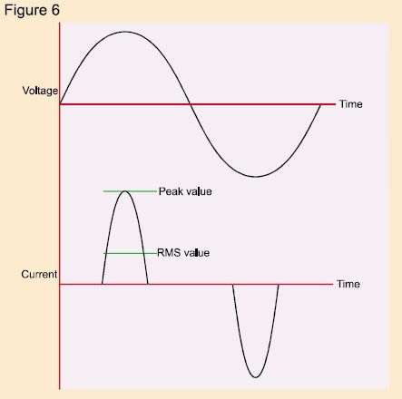
A typical switch mode power supply will take current from the AC supply as shown in fig. 6.
It is clear that the crest factor of the current waveform depicted is much greater than 1.414 – indeed most switch mode power supplies and motor speed controllers have a current crest factor of 3 or greater.
It follows therefore that a large current crest factor must put additional stress on equipment supplying such load as the equipment must be capable of supplying the large peak currents associated with the distorted waveform.
This is particularly relevant were a limited impedance power source, such as a standby inverter, is supplying the load.
It is thus clear that, where AC equipment is involved it is important to know the crest factor of the current drawn as well as its RMS current.
6. Harmonic Distortion
If a load introduces distortion of the current waveform it is useful, in addition to knowing the crest factor, to quantify the level of distortion of the wave shape.
Harmonic distortion occurs when a non-sinusoidal current waveform contains frequencies that are integral multiples of the fundamental frequency. These harmonics can lead to additional losses and stress on the power system.
Observation on an oscilloscope will indicate distortion but not the level of distortion.
It can be shown by Fourier analysis that a non-sinusoidal current waveform consists of a fundamental component at the supply frequency plus a series of harmonics (i.e. components at frequencies that are integral multiples of the supply frequency).
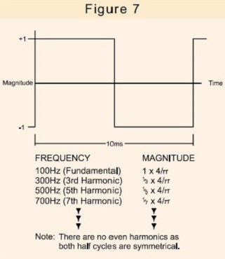
For example a 100 Hz square wave consists of the components shown in fig. 7.
A square wave is clearly very distorted compared to a pure sine wave. However the current waveform drawn by for example a SMPS, a lamp dimmer or even a speed controlled washing machine motor can contain harmonics of even greater significance.
Fig 8. Shows the current drawn by a popular SMPS model together with the harmonic content of that current.
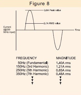
The only useful current is the fundamental component of current, as it is only this that can generate useful power.
The additional harmonic current not only flows within the power supply itself, but in all of the distribution cables, transformers and switch gear associated with the power supply and will thus cause additional loss.
High harmonic content can affect power quality and efficiency and there is an increasing awareness of the need to limit the level of harmonics that equipment can produce. Controls exist in many territories to provide mandatory limits on the level of harmonic current permitted for certain types of load.
Such regulatory controls are becoming more widespread with the use of internationally recognized standards such as IEC555, soon to be replaced with IEC1000-3.
Thus there is a need for an increased awareness amongst equipment designers as to whether their products generate harmonics and at what level.
7. Measurement of AC Parameters
For AC power suppliers and equipment makers, the discussed AC parameters are essential. But a lot of the measurement instruments on the market today can be difficult to operate or lack sufficient functionality and accuracy, especially when working with distorted or noisy inputs.
Voltech Instruments addresses these challenges by developing and manufacturing advanced power measurement instrumentation. Our solutions cater to a wide spectrum of needs, ranging from general-purpose power measurement to intricate and high-demand power analysis tasks.