Test Suggestions for Ferrite Transformers
A tech note describing theory of Ferrite Transformers
1. Introduction to Testing Ferrite Transformers
As electronic products utilise higher frequency techniques to reduce size and improve efficiency, ferrite cores are used in an increasing proportion of transformer designs.
Transformer manufacturers must therefore meet a need for smaller transformers designed to operate at higher frequencies, which introduces additional demands on both manufacturing and testing methods.
These issues apply to a wide range of common applications including switched mode power supplies, lighting ballasts, inverter drives, audio and telecommunications equipment and many more.
Today's need for the proven performance of all components within a product has resulted in a demand for each and every transformer to be more thoroughly tested than traditionally expected.
In the following pages, we will consider the range of tests that are appropriate for thorough testing of ferrite transformer designs and we begin with a review of the components present in a common transformer.
FIGURE 1
Schematic of a simple two winding transformer connected to the four wire Kelvin nodes of an AT series transformer tester.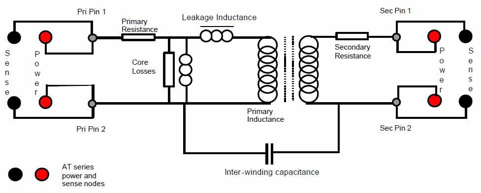
From the schematic in figure 1, it can be seen that even the most simple of transformers includes quite a complex combination of resistive and reactive components.
In order to establish with confidence that a transformer has been manufactured correctly, it is necessary to execute a range of tests that combine to provide an assurance that the materials used and manufacturing process executed results in transformers that meet the design specification.
2. R: Resistance
Ensures that the gauge of copper being used for each winding is correct.
Unit of measurement, Ohms. Range 10 mOhms to 10 MOhms
All windings are tested individually ensuring that there are no windings with an insufficient gauge of copper to carry the required current.
3. LS: Series inductance
Ensures the correct core material has been used and that the number of turns is correct.
Unit of measurement, Henries. Range 1 nH to 1 MH with signal level from 1 mV to 5V @ 20 Hz to 3 MHz.
Different core materials exhibit different permeability and therefore a different value of inductance for a particular number of turns. With the correct number of turns, inductance provides a measure of the core materials ability to maintain the required magnetic flux without saturation.
Figure 3 Example test entry screen for inductance using the Editor program.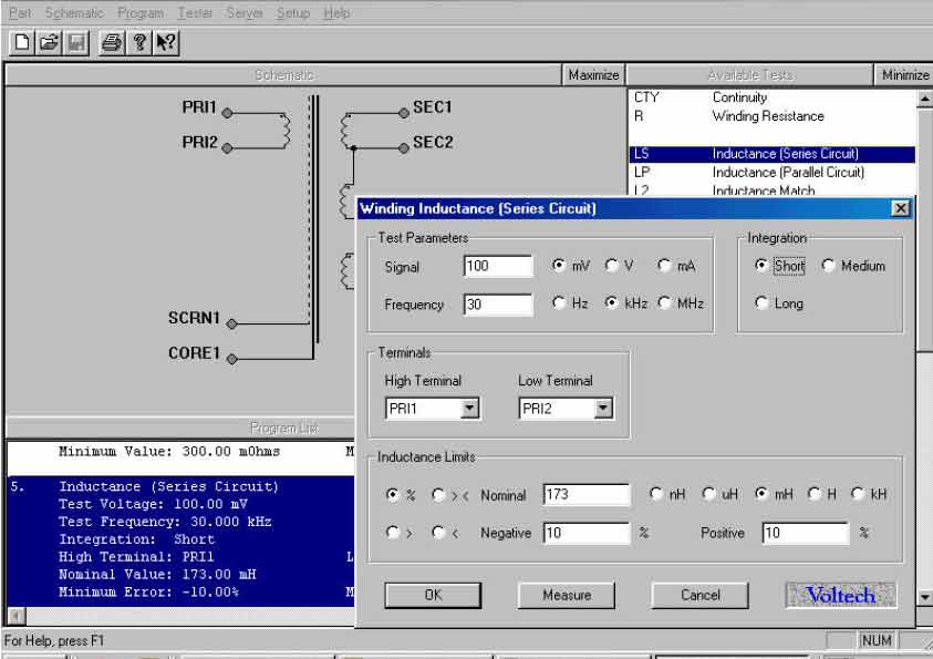
4. QL: Quality Factor
Ensures that core material and its assembly is correct
Unit of measurement, Q. Range 0.001 to 1000 with signal level from 1 mV to 5V @ 20 Hz to 3MHz
Quality factor represents the efficiency of an inductor as the ratio of energy stored to energy wasted and is derived from the equation L / (R SQRT(LC) ). It can be seen that higher Q values are obtained when the inductive component is large relative to the resistive and capacitive components.
Figure 4 Example test entry screen for Q Factor using the Editor program.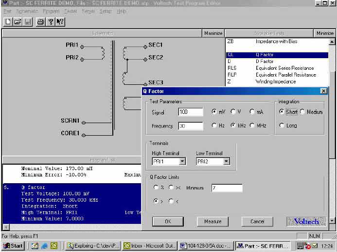
5. ANGL: Angle of impedance
Ensures that the core material, wire resistance, number of turns and inter-winding capacitance combine to meet design specifications.
Unit of measurement, Degrees. Range -360° to +360° with a signal level from 1 mV to 5V @ 20 Hz to 3MHz.
For transformers in applications that operate over a wide frequency range, e.g. audio transformers, the designer or the production department may have to measure the phase angle between the real impedance (resistive (R)) and imaginary impedance (inductive or capacitive (jXs)). The sum of R and jXs is commonly referred to as Z (total impedance).
As the applied frequency is increased on an inductor the impedance increases and the impedance phase angle decreases up to the point of self-resonance, at this point the impedance phase angle is zero (also the highest impedance value).
Figure 5 Example test entry screen for Phase Angle using the Editor program.
6. LL: Leakage inductance
Ensures that windings are positioned correctly on the bobbin and that any air gap included in the core design is the correct size.
Unit of measurement, Henries. Range 1 nH to 1 kH with signal level from 1 mV to 5V @ 20 Hz to 3 MHz
Leakage inductance is the inductive component attributable to magnetic flux that does not link primary to secondary windings. Designs may require a specific value of leakage inductance for the correct operation of the circuit into which the transformer will be fitted or it may be necessary to keep the value very low. Measurement of leakage inductance requires the application of a short circuit to secondary windings and this can often present problems in a production environment. The AT series testers eliminate these problems with a unique measurement technique that is described in detail in a separate technical note VPN: 104-105.
Figure 6 Example test entry screen for leakage inductance using the Editor program.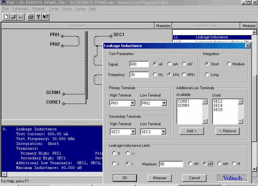
7. C: Inter-winding capacitance
Ensures that the insulation thickness between windings is correct.
Unit of measurement, Farads. Range 100 fF to 1 mF with signal level from 1 mV to 5V @ 20 Hz to 3MHz
Capacitance occurs in inductors and transformers due to the physical proximity of electrostatic coupling between wire within a winding.
Capacitance also exists between separate windings from primary to secondary or secondary-to secondary.
Figure 7 Example test entry screen for capacitance using the Editor program.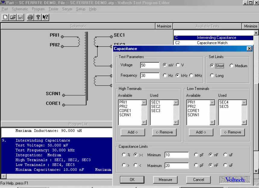
8. TR: Turns ratio
Ensures that the number of turns on each winding and the winding polarity meet specification.
Unit of measurement, Decimal Ratio. 1:100 k to 100 k:1 with a signal level from 1 mV to 5V @ 20 Hz to 3MHz
Turns ratio is measured to establish that the number of turns on primary and secondary windings are correct and therefore the required secondary voltages are achieved when the transformer is in use. It is important to remember that the various transformer losses shown figure 1 will result in a voltage ratio that does not correspond exactly with the ratio of physical turns present on the windings. The AT series testers include the ability to calculate turns from the ratio of inductance (TRL) which overcomes errors attributable to core loss and leakage inductance.
This and other turn ratio considerations are described in a separate technical note VPN: 104-113.
Figure 8 Example test entry screen for Turns Ratio using the Editor program.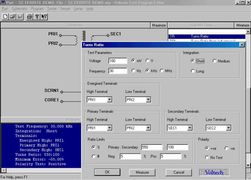
9. SURG: High voltage surge testing
Ensures that the insulation material around the copper wire (usually lacquer) has not been damaged during manufacture introducing the risk of an inter-winding short circuit.
Unit of measurement, mV Seconds. Range 1 mVs to 1 kVs with an impulse signal level from 100V to 5kV.
Transformers with a high number of turns using fine wire are vulnerable to insulation damage. Damage to the insulation material during production is very difficult to detect as there may not be a total short circuit and the voltage applied during turns testing will not be sufficient to bridge this partial short. However, during operation within the finished product, the transformer is exposed to much higher voltages which can cause a corona arc at the point of damage or the heating effect of normal use may cause a short circuit after a short period of time.
By connecting a charged capacitor within the AT3600 to a transformer winding, the winding is exposed to an impulse voltage and by measuring the area under the decaying oscillation, it is possible to establish if a breakdown between turns of the winding has occurred. The diagram below illustrates the decaying oscillation of a transformer winding with no insulation damage versus the same winding with damaged insulation.
Figure 9 Surge waveform examples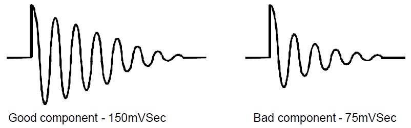
By computing the volt-second product under the curve, the AT3600 provides a numeric quantity by which to establish good or bad components. This gives the benefit of shorted turns detection using an impulse voltage technique, while avoiding the potential errors inherent in user interpretation of complex waveforms.
Figure 10 Example test entry screen for Surge Stress using the Editor program.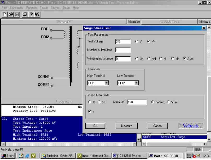
10. IR: Insulation Resistance
Ensures that the isolation between windings meets the required specification
Unit of measurement, Ohms. Range 1 MOhms to 100 GOhms with a signal level from 100V to 7kV (AT5600 + AT3600) or 500 V (ATi).~
Using a DC high voltage generator and DC current measurement system, the value of resistance is calculated.
Figure 11 Example test entry screen for Insulation Resistance using the Editor program.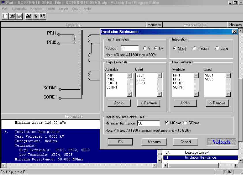
11. HPAC: High Voltage AC safety testing
Ensures that the windings are positioned correctly with the correct materials to provide the required level of safety isolation.
Unit of measurement, Amps. Range 10uA to 10 mA with a signal level from 100 V AC to 5 kV AC.
All transformers that provide isolation from an AC power system must be tested to confirm their ability to withstand safety-testing voltages without breakdown. In order to meet testing regulations, it is necessary to provide evidence that the test voltage is maintained during the test period and the AT3600/AT5600 achieves this by measuring and controlling the applied voltage throughout the complete duration of test.
Figure 12 Example test entry screen for HPAC using the Editor program.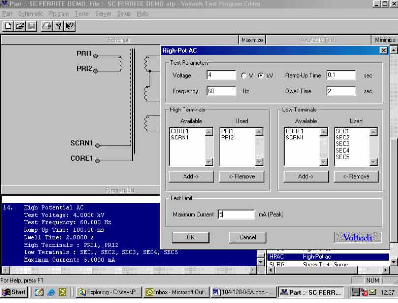
12. Ferrite Testing Conclusions
It can be seen that the appropriate range of tests will provide complete assurance that all materials and production processes within a transformer are correct.
This in turn will guarantee that each and every transformer tested is known to fully meet the required specification.
Such thorough testing here has historically been to costly, too difficult or too time consuming.
However the AT series testers provide a cost effective, easy to use and fast solution.
The complete test shown above was executed by the AT tester at a speed of 1.2 seconds, with the single touch of a button.