
PCV-2-564-08L
Worked Example of Suitable Tests
Power Inductors are used in a variety of applications as part of an LC combination to filter the output of a circuit.
Typical applications are DC-DC converters and on the output of most SMPS topologies.
Correct selection and operation of the inductor will smooth the current into the capacitor, protecting it from excessive ripple, allowing a smaller cheaper output capacitor to be used.
These inductors also need to have a low DC resistance to minimize self-heating, as excess heat will stop the magnetic function of a core, and also bleed energy from the circuit.
They also need to be able to operate inductively in the presence of DC currents, i.e. still be able to store and release energy in the core without saturating
Coilcraft manufacture a large range of transformers and inductors.
The Coilcraft PCV-2-564-08L is a great example of this type of power inductor, shown to the left.
PCV-2-564-08L
The inductor is easily represented on the AT EDITOR program via a single winding.

Editor Schematic
The 0.054 inch/1.37 mm thick pins of the PCV 2-564-08L make it ideal for a Kelvin pin fixture, which will allow for true Kelvin measurements by allowing any effect of the fixture wiring to be compensated out.
As DC power chokes are typically specified with very low resistances it is important to be able to measure and monitor this in production.
As we will be testing DC BIAS over 400 mA DC, we will also use a Voltech DC1000 Bias unit to supply the 7.00 Amps DC.
This DC1000 is connected across terminals A and B via the fixture.
The AT test program then automatically controls both the AT tester and the DC1000 without the need for user intervention.

Press fit fixturing into two kelvin clips.
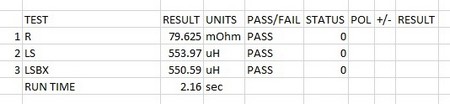
The DC resistance of the inductor is checked first with the limits set to check that it is below the nominal 90 mOhms
Next, Inductance is checked at 15.75 kHz as a check of the number of turns and core material.
Finally the DC1000 is activated by the LSBX test to provide 7 Amps DC, and the inductance checked again to prove it is constant under DC bias.
|
# |
Test |
Description |
Pins and Conditions |
Reason |
| 1 | R | DC resistance | Check winding resistance <90 mOhms as per spec | To check the winding resistance is below a maximum. Also acts as a check of correct wire gauge and good termination. |
| 2 | LS | Series Inductance | Check inductance at 15.75 kHz 100mV is 560 uH +/- 10% | To check the correct number of turns and correct operation of the core material |
| 3 | LSBX | Series Inductance with BIAS | Check inductance at 15.75 kHz 100mV is 560 uH +/- 10% in presence of 7 A DC bias as per spec | To check the correct number of turns and correct operation of the core material under DC Bias |
| AT5600 Run time 2.16 sec | ||||
| (AT3600 Run time 4.40 sec) |
NOTES:
The DC1000 can also be used in the design phase with a variety of LCR meters to prove proof of concept.
At this stage it is desirable to test over a wide variety of frequencies and DC bias currents, in excess of normal production testing, to validate a design.
See the link at the bottom of the page to find out more.
Thank you for subscribing!
You’ll receive a confirmation email shortly.