
Eaton CTX210607
Worked Example of Suitable Tests
Cold Cathode Fluorescent Lamp (CCFL) Inverter Transformers are widely used to convert a low DC supply to a high voltage AC to drive, for example, LCD back-lights.
They employ a variant of SMPS technology to switch the DC using transistors (in a push-pull configuration) at high frequencies (40-80 kHz in our example) into the primary.
A feedback winding is used to provide positive feedback to make the circuit oscillate
Usually, the secondary winding is deliberately designed to have a set leakage inductance, which then resonates with a capacitor on the secondary to drive the lighting tube.
As the transformer is such an integral part of the operation of circuit, measurement of parameters such as leakage inductance are important as well as the usual parameters of winding resistance and turns ratio. The transformer also needs to provide isolation, especially as the circuit first generates a higher “strike” voltage to start the tube, before settling into a constant running state.
Eaton CTX210607
Eaton make a variety of versatile CCFL transformers for these operations. Here, we will examine the CTX210607.
Note that the secondary is wound in 4 sections.
This is so that the Volts per Turn drop is spread across 4 separate areas, which improves inter-winding isolation under the high potential differences without having to resort to heavily insulated wire.
The primary and feedback coils are also separate. This separation controls the deliberate introduction of leakage inductance discussed earlier.

CTX210607 schematic
The AT Editor software representation of the part is shown here to the left.

AT Editor schematic
The transformer package is a standard surface mount design, and as such is not suitable for Kelvin pins.
The fixturing shown here is a zero insertion force socket (ZIF) in which pairs of blades are closed onto each pin from the side.
This has the advantage of not putting the part under any mechanical strain whilst still maintaining a true Kelvin contact to each winding.

ZIF (zero insertion socket) on 91-184 fixture

ZIF (zero insertion socket) on 91-184 fixture
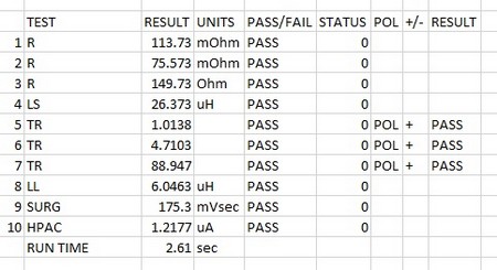
The winding resistances are checked first to validate continuity and connection.
This is followed by and inductance check at the operating frequency on the primary.
This is followed by three checks of the turns ratios; half primary to half primary, primary to feedback and primary to secondary.
Note that the last test is performed by energizing the secondary as for optimum accuracy it is best practice to energise the winding with the greatest number of turns.
We then test leakage inductance between primary and secondary; we find that the leakage is roughly 25% of the primary inductance as this is probably a deliberate design factor in the operation of the output LC circuit.
For this we have used percentage limits around a nominal LL value, rather that checking LL is just below a maximum as is normally the case.
As the secondary is made from fine wire, and subject to high voltages and even higher “strike” voltages to start the gas tube, we next use the SURG test to check for any Inter-winding coil weaknesses. This is performed by injecting high voltage pulses and measuring the characteristic ringing decay on the secondary winding. An empirical nominal from a known good transformer is selected for our limits. Any breakdown in the insulation will result in energy loss and hence a different decay response.
See the link at the end of this section for more information on SURGE testing.
Finally a HI POT test at 2 kV AC is used to check primary to secondary isolation.
|
# |
Test |
Description |
Pins and Conditions |
Reason |
| 1 | R | DC resistance | pin 1-3, limits <135 mOhms | To check the total primary winding resistance is below a maximum. Also acts as a check of correct wire gauge and good termination. |
| 2 | R | DC resistance | pin 4-5, limits <100 mOhms | To check the feedback winding resistance is below a maximum. Also acts as a check of correct wire gauge and good termination. |
| 3 | R | DC resistance | pin 10-6, limits <175 Ohms | To check the secondary winding resistance is below a maximum. Also acts as a check of correct wire gauge and good termination. |
| 4 | LS | Series Inductance | Pin 1-3, 100mV, 20 kHz, nominal 27 uH +/- 10% (as per published spec) | Inductance as seen by the primary. To check the correct number of turns and correct operation of the core material |
| 5 | TR | Turns Ratio | Energise pins 1-3, 100 mV 40 kHz, check Turns ratio and phase 1-2:2-3 to be 1:1 +/- 5% | To check correct ratio of windings between the two halves of the primary to the centre tap. |
| 6 | TR | Turns Ratio | Energise pins 1-3, 100 mV 40 kHz, check Turns ratio and phase 1-3:4-5 to be 4.6:1 +/- 5% | To check correct ratio of windings from whole of the primary to the feedback winding. |
| 7 | TR | Turns Ratio | Energise pins 10-6, 100 mV 10 kHz, check Turns ratio and phase 10-6:1:3 to be 86:1 +/- 5% | To check correct ratio of windings from secondary to primary. The winding with the most turns is energised as this is best practice for optimum accuracy. |
| 8 | LL | Leakage Inductance | Pins 1-3 Hi, Pins 10-6 Low, 100 mV, 40 kHz , check leakage is below 6.5 uH | To check leakage is below specified limit as a validation of correct placement and operation of windings. |
| 9 | SURG | Surge Stress Test | Energise pins 10-6, 4000 V, 5 pulses. Check that mVs product is 166 mVs +/- 30% | To check for weak points in the secondary inter turn insulation, to prove longevity of the part over its operational life. |
| 10 | HPAC | AC Hi-Pot | 2 kV AC,50Hz, 1 second, Pins 1,2,3,4,5 High, Pins 10,6 LO. Check <15 mA current | To check isolation as per datasheet. |
| AT5600 Run time 2.61 sec | ||||
| (AT3600 Run time 5.49 sec) |
Notes:
As the Leakage Inductance is governed by turns ratio, and core response (already covered by TR and LS) and the physical positioning of the windings, some customers (using automatic winding methods) may have enough confidence in winding positioning to only audit this parameter occasionally, rather then on every part tested.
Thank you for subscribing!
You’ll receive a confirmation email shortly.