Hi-Pot Testing for Transformers
An explanation of AC and DC high voltage safety testing, and answers to some frequently asked questions
1) Hi-Pot Testing - How and Why?
Virtually all transformers work on the principle of inductance where a primary voltage is induced in a totally isolated secondary because of the linkage of flux across the core.
Despite being a mature technology transformers are still widely used, due to the unique combination of three properties ;
1) Accurate Voltage transformation.
2) No active or solid state parts - easy to manufacture.
3) Excellent isolation due to physical separation of windings.
It is obviously critical to have each winding well isolated for it to perform at normal conditions, and guarantee long term safety and reliability.
A common reason for transformer failure is the poor isolation of parts within the build due to accidental voids or breaks in the insulation or cracks in the winding wire enamel
Mechanical faults such as these can occur at any time during manufacture, transportation and handling.
They are also impossible to detect visually, or even detect using traditional low voltage (0-240V) characterization of a transformers operation.
Hence the testing of isolation has become a necessity, and furthermore is always 100% tested on every part, never assumed from design specs or by test sampling of production.
2) Factors Influencing Hi-Pot Test Voltage.
To address and catch occurrences of this problem, HIPOT testing is performed both
In the design phase, to confirm the suitability of the choice of materials and design before mass manufacture. and,
In the production phase, to confirm the ongoing repeatability of the processes
To guarantee the safety of operation at time of manufacture, and also over the lifetime of the transformer, designs are always tested far in excess of their normal working voltages.
The working voltage is usually defined as the maximum voltage that can be present under normal conditions for the parts continuous operation.
It is general industry standard practice to then test for isolation at twice the operating voltage, plus an additional 1000V for a large margin of safety.
This extra 1000V covers the extra stress caused by inrush and back EMF transients seen at power on and power off.
The extra margin also covers the aging of the transformer over time, and any possible changes to the environmental conditions it is being operated under (temperature and humidity can both affect the isolation over time)
For example a 240V transformer would be tested from primary to secondary at 2 x 240 V +1000 V =1480 V (typically 1.5Kv).
Of course, the main driving factor for the isolation needed, and hence test voltage needed, will always be the end application and any industry UL / IEC standard which you are trying to conform to.
This then informs the design choices made and testing protocol developed.
Historically, the IEC or UL standards were separate for IT and audio/ A.V. equipment
These were ;
IEC 60950 Information technology equipment – Safety
IEC 60065 Audio, video and similar electronic apparatus - Safety
However, these have been superseded in 2020 by a new combined standard as technology advances have made the division between these two less meaningful.
This new standard is;
62368 Audio/video, information and communication technology equipment.
This new combined standard has more focus on safety as a general topic, as well as extended the scope to include bought-in sub-assemblies (such as transformers) which makes the need for hipot testing even more critical in all parts of the supply chain.
3) How is a Hi-Pot test performed ?
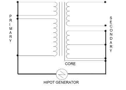
A HIPOT test is performed by applying a high voltage signal between a chosen shorted HI side to a shorted LO side of the transformer as shown in the diagram below.
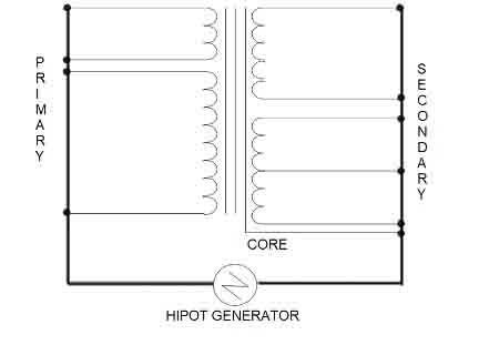
Typically, and as an absolute bare minimum, one would test all the primaries against all the secondaries as shown.
However additional tests for primary and secondaries to the core, or one primary against another primary may also be desirable in the case of more complex designs.
The voltage level applied for the test is based on the expected design insulation of the part which in turn is a function of winding wire used and physical separation of the windings.
After applying the high voltage over a specified ramp up period, the test equipment will measure the current between the high and low over a defined period of time, (referred as DWELL time)
If during this time the measured current flowing exceeds a defined limit, the part is classified as a failure.
This failure could be from either
1) A sudden catastrophic failure where the insulation has permanently broken down resulting in a large instantaneous current spike (“flashover”)
or
2) A current measurement that is stable, but still in excess of your chosen test limit (eg, reading 2.2 mA when the limit of acceptability is 1mA)
It is also important to note that any type of Hi-Pot testing is potentially destructive to the part.
The only way to find weak areas in the wire enamel (or any insulation barrier) is by testing at a high enough voltage to give confidence that the insulation can withstand any voltage spikes or transients it may encounter in its operating lifespan.
External standards will guide you on the required voltage level to meet that specific standard. Your design may be able to withstand even higher voltages, but care should be taken if increasing your test voltage level as you will eventually reach the natural design limit of the parts used.
4) Types of Hi-Pot failure mode
As stated earlier, a transformer can fail a hi-pot test in one of two possible ways.
The AT5600 + AT3600 both have two distinct methods for detecting these
4.1) Flash over.
A sudden flash over is detected by a hardware trip circuit independent of the AT measurement circuits and firmware.
This results in a 3400 error code indicating a hard flashover.
In these cases, any measurement reading is invalid as stable conditions were not met, making any reading invalid.
Depending on the time taken to trip the AT could report this as anything from a 0.00 mA reading, or a large 30mA+ reading.
In all cases a 3400 trip code will be shown and the test fails.
These causes also usually result in a visible flash over or audible sparking crack as the part breaks down.
4.2) Measurement Failure
The second failure reason is if the current measurement is above your chosen acceptance limits.
In these cases, the requested voltage is achieved and maintained for the whole test time, and the largest current measured during this period is returned as the numerical result.
In these cases the error code is returned as “0000” indicating that stable conditions were met, but the test can still fail if the largest current flow (say 2.2 mA) was in excess of the maximum specified for the test (say 1.0 mA).
5) Should I hipot test with AC or DC?
The choice of AC o r Dc testing is largely driven by the standard you are testing to, and any specific customer requests.
AC is usually the preferred method in most cases, except in case where you are testing a finished assembly (e.g. EMC filters) that may have real capacitors fitted.
5.1) HPAC - AC hipot testing ( 0-5 KV AC, 50-1000 Hz )
With AC testing, a long ramp up time is not usually needed, and the decay of any charge after the test is finished usually much quicker as the natural capacitance of the transformer is not charged
However, the measured current will include both the effect of the real (very high) resistive characteristic of the transformer and the effect of the interwinding capacitive reactance.
As long as this is understood, and the capacitive current effect is below your total current test limit this may still be preferred due to the time saving on ramp up time.
5.2) HPDC - DC hipot testing ( 0-7 KV DC )
With a DC hipot signal the ramp up time may need to be increased to allow the natural intrinsic capacitance of the transformer to stabilize.
If it is too fast then it may result in excessive current flow and indicate false failure.
However, this method does give a clear indication of the true resistive current flow as the AC effects are removed.
Both the HPAC and HPDC tests on the Voltech AT5600 automatically switch in a bleed resistor after every Hi-pot test to remove any charge left in the UUT, for safety.
This process is intelligent, so you can add extra test time in the case of HIPOT DC testing with larger and more capacitive transformers.
6) AT5600 HIPOT Testing Best practices
There are different issues that could cause the HIPOT testing to fail aside from the obvious reasons of faulty insulation and assembly.
One of the potential reasons could be how the HIPOT testing has been designed and executed.
Any measurement requires stable and controlled conditions for the measured results to be repeatable, stable and hence a meaningful indication of performance.
6.1) Ramp up time
The speed at which the large test voltage is applied should be considered so that the maximum is achieved under stable control.
This is especially true of larger test parts (e.g. toroidal transformers or E-core laminates), where a ramp up time of 0.5-2.0 seconds may be needed depending on the size and capacitance of the transformer.
6.2) Avoid unconnected floating nodes during Hi-Pot testing.
For best practice, all terminals in the component should be selected as either HIGH or LOW to avoid any windings to float.
Unconnected terminals or nodes will tend to float to an uncontrolled potential, somewhere between the 0V Low and the energized HIGH voltage.
This is undesirable from a measurement point of view as this uncontrolled winding can affect the stability of the already very small current measurement being made between the chosen terminals.
It is also undesirable from a test safety point and unit protection of view as floating windings can remain charged after the test is completed. Again this is especially true for physically larger transformers.
This charge could then possibly affect later low voltage tests on those floating windings or at worst cause an accidental discharge into the AT tester when it attempts to connect the winding for a later test.
7) AT5600 HIPOT generator and the IEC standard
The AT5600 is designed to meet the transformer testing requirements of IEC 62368-1 and IEC 61010-1 and the UL equivalents.
These standards do not require power for production hi-pot testing of the transformers, but only specify the test voltage and duration of test ( also referred to as the “dwell time.”)
The IEC standards allow the test duration to be reduced to 1-2 seconds if the test voltage is increased by 20% above requirement.
This obviously gives a large improvement in test throughput for manufacturers, as long as each of the specific designs can withstand the extra 20% of test voltage.
This would obviously need checking by batch pre-testing to confirm suitability, before fully implementing.
The IEC standard contains derating graphs which explain in more detail the allowed reduction of test time, against the corresponding increase of test voltage needed.
The AT5600 HIPOT generator has a rating of 250VA..
Even with a winding capacitance as high as 10nF, the required current at 5 kV 60Hz is only 19.1 mA, corresponding to a VA requirement of only 96 VA, so the 250VA has plenty of excess capacity to generate the voltages required for even the largest transformers.
8) FAQ - Frequently Asked Questions.
8.1) I tested the same part with two AT5600s, both units read differently for the HPAC/HPDC
Unit 1 - 3.2 uA
Unit 2 - 10.0 uA
The AT5600s do not read the same small current, what should I do?
Answer:
As with any electrical measurement, as the signal tends to zero, the possible error in the reading will increase.
HI-pot measurements, by their very nature, are measuring very small currents.
An ideal transformer would give a HIPOT current reading of zero.
It is a common misconception to think of these measurements as you would a more typical DCR reading of say 2 ohms, where you expect stability and repeatability.
However, since the current is very low, you should expect that such very small readings would be susceptible to the inherent noise floor of the unit.
This could give you a range of readings for different test equipment, but that should still be well below the requirement requirement or your specified limits.
A bad isolation (e.g., dead short, weak enamel between windings etc.) would give you excessive current readings greater than your limits or even a hard flash over / 3400 trip for genuine bad parts.
Some test equipment manufacturers choose to return results below a set number (say 20uA) as a hard “0.00”, but we have chosen to always report a number as proof of measurement, even if such small results may be subject to a large (eg + / - 100%) error tolerance.
It is therefore normal to get slightly different HPAC/HPDC on different AT Units in cases where the part under test is a good isolator, and the current measurement is inherently very small.
8.2) My AT5600 gives 3400 error codes even if I reduce the HIPOT requested voltage.
What are the troubleshooting steps to fix this problem?
Answer:
There are things that could be causing the 3400 TRIP on the AT5600.
1, Fixture plate used - the fixture itself could be contaminated, or does not have enough clearance for the voltage stand off required. (a good rule of thumb is at least 1mm minimum per 1000V standoff)
2, A Genuine bad part.
3, Large natural capacitance of the part (for larger transformers - in these cases increase the RAMP UP time).
The trip mechanism on the AT5600 during the HIPOT test engages when a dead short or an excessive current has been measured.
If the trip happens in multiple parts, that you suspect are actually "good", then you should check the fixture being used.
You can quickly test the fixture and unit by the following two tests.
1, Running the program (ideally 4-5 times) and directly from the AT Editor, with the fixture fitted but NO UUT fitted.
You will expect to get failure on the measurement tests (eg, R, LS, RLS, Z, MAGI etc.) as no part is present.
However, an HPAC or HPDC tests you have programmed should pass
If the HPAC/HPDC tests fail with no UUT fitted, then the fixture is not properly isolating the nodes.
Examine the fixture for
A, signs of contamination on the top surface.
B, the separation of the wiring within the fixture - wires should not cross over each other, as this can result in “cross-talk”
2, Run the program on the unit with NO fixture, and NO UTT connected.
As above this will test the hipot integrity of the unit
You will expect to get failure on the measurement tests (eg, R, LS, RLS, Z, MAGI etc) as no part is present.
However, an HPAC or HPDC tests you have programmed should pas
If you have a HPAC or HPDC failure with no fixture connected, then please contact us.
8.3) My AT5600 Screen suddenly flickers during the HIPOT test, is my unit faulty?
Answer:
Any high voltage test (especially with larger signals as high as 3- 5kV), can result in EMI emissions through the air.
Due to the relative closeness of your UUT to the AT5600 screen, the large screen of the AT5600 could pick-up this energy.
This can cause the screen to flicker during these tests, but is only a visual effect and has no effect on the digital operation of the unit.
As long as the test is still controlled, maintained, and the AT5600 is able to finish the test, this is expected behavior and should not be cause for concern..