DC Chokes - Background and Measurements
This documents outlines test methods for all types of DC Chokes
1, What Is DC Bias And When Should It Be Tested?
In the context of a transformer or choke, DC bias describes a constant current element that is added to the AC signal.
Many wound components must operate with DC currents flowing through them and, during the design stage, it is necessary to establish that the component will function correctly with the specified current.
In the case of production testing however, it is possible to confirm the correct assembly, and therefore correct operation of a wound component, without applying a DC bias.
However, For best confidence, you should check with DC bias present, using a DC bias unit such as DC1000A to guarantee correct operation in each and every pat.
The Voltech AT5600 allows for integration of DC1000A and automatic audit of DC performance.
2, Low-current And High-current Applications
In some cases, the DC bias current is small (under 400 mA).
As, for example, in telecom transformers where a winding is in series with the DC power supply current to the telephone.
In other cases, the DC bias current is much larger, such as in inductors used as output filters on power supplies:
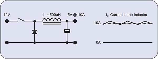
In all these cases, the wound component must retain a specified inductance with the rated D current flowing in the winding.
3, Design Considerations
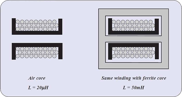
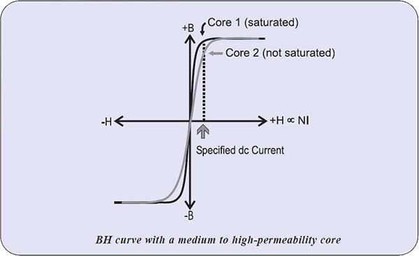
Magnetic materials such as iron and ferrite generally have a high value of permeability, i.e., a coil of a given number of turns will have much more inductance than the same core in air.
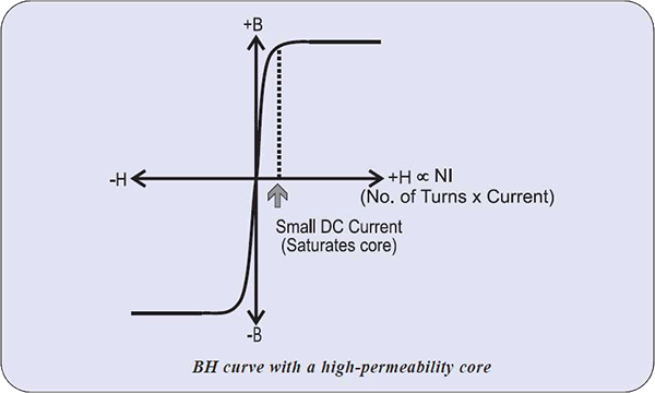
However, a wound component with a high-permeability core has a very steep B-H curve and, therefore, can tolerate only a very small DC bias current or the core will saturate.
If the core saturates, the inductance will fall to a very low value.
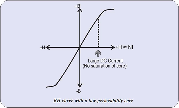
In order to make a coil that will operate with higher values of dc bias current, it is necessary to reduce the permeability of the core.
This is done by introducing air gaps in the magnetic circuit, either by using a physical spacing or by using a core made of a composite of magnetic and non-magnetic materials (providing the effect of air gaps).
Cores with air gaps have a much lower overall permeability and can tolerate much larger DC currents before saturating:
4, DC Bias Testing
4.1 Cores for small DC bias currents
Wound components for small DC bias currents are generally constructed with cores having medium to high permeability.
The value of permeability of such cores varies from batch to batch, as it depends on the manufacturing process of the core itself.
This variation results in a wide tolerance of the measured inductance of the winding, which is seen in the wide tolerance of inductance constant (AL) of core manufacturers specifications.
This variation in inductance results in the possibility that some coils will be able to tolerate the specified dc bias current and some will not:
The only sure way of verifying whether the coil can operate with specified dc current is to measure the inductance with this small dc bias current flowing, ensuring that the inductance is at least the specified minimum value.
The on board LSB LPB and ZB tests of the AT5600 allow up to 1 Amps DC bias without the need for an external bias source.
4.2 Cores for larger DC bias currents
As mentioned earlier, coils for higher DC bias currents (greater than about 400 mA) have a low permeability core due to air gaps.
As the air gap is increased the permeability and, therefore, inductance falls, and the DC current capability increases, as shown for a typical air-gapped ferrite E-Core below. (The number of turns is the same for each value.)
|
Air Gap |
Inductance |
DC Current Capability |
| 0.0 mm | 19.1 mH | 0.36 A |
| 0.2 mm | 9.2 mH | 1.37 A |
| 0.5 mm | 5.9 mH | 2.06 A |
| 1.0 mm | 4.9 mH | 2.53 A |
| 2.0 mm | 4.1 mH | 3.18 A |
| 5.0 mm | 3.2 mH | 4.00 A |
Provided that the core does not saturate, which is established during the design phase, the value of inductance for any transformer will be the same with or without DC bias applied.
To illustrate this, the graph below shows inductance measurements obtained from the transformer in the table above with no DC bias, compared to the same transformer with the specified dc bias applied.
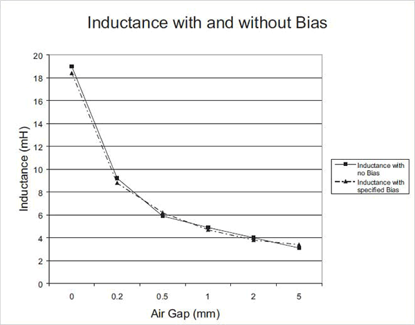
For cores with larger air gaps, the permeability and, therefore, the inductance are determined predominately by the size of the gap and are much less affected by variations in the core material.
This results in the variation in inductance being much smaller with a gapped core, as the gap has a much more constant permeability than the magnetic material itself. The value of inductance will therefore be predictable within a tight tolerance.
It follows, therefore, that a measurement of inductance (without DC bias) of such a coil provides the necessary check that the core has the correct air gap and, therefore, has the ability to operate at the specified DC current.
5, DC Bias Conclusions
All DC chokes use low-permeability cores, either powdered iron or ferrite cores with a substantial air gap.
A low permeability is essential to prevent the core saturating with a large DC current.
Inductance is a measure of the slope of the B-H curve.
A core with high permeability can have a slope or inductance value with a wide tolerance.
The low permeability of cores with an air gap or made of powdered iron causes these cores to exhibit an inductance that can be specified within very tight limits.
|
Cores for low dc bias currents (<400 mA) |
Cores for high dc bias currents (>400 mA) |
|
Measure Inductance with specified dc current in winding. Accept wide limits on range of inductance values but result must be greater than a certain minimum value. |
Measure inductance without dc bias current. Set limits as tight as possible e.g. 5% as means to verify gap. |
It is essential during design testing to confirm that a DC choke exhibits the proper inductance at rated DC current.
In production testing, however, some DC chokes can be tested by checking the inductance without DC bias, but specifying tight limits will verify that the core has the correct turns and, therefore, the correct slope to give the required inductance at the specified DC current.