Relay Switching - AT Tester Operation
The technical background to the AT Series testers
Explains how the nodes operate during testing to give fast and accurate 4-wire measurements
Relay Switching Techniques - The 20-Node Relay Matrix
The Voltech AT5600 uses a 20-node relay matrix, terminating in pairs of spring probes, to allow standard fixtures to be connected to the unit.
Each pair of spring probes (a node) connects to four high-voltage relays, configured for full Kelvin (4-wire) measurement.
Two of these relays, 'Source Hi' and 'Source Lo' (the "power" pair), are energized to supply the voltage/current source to the component under test.
The remaining two relays, 'Measure Hi' and 'Measure Lo' (the "sense" pair), are energized to route the voltage/current source to the measure circuit.
This configuration is shown below, in Figure 1, for one of the nodes connected to one end of a transformer winding under test.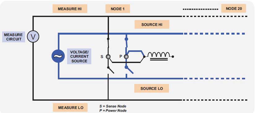
Figure 1
This type of Kelvin relay arrangement for each of the 20 nodes is fully controlled by the AT5600 and is programmable through the supplied AT Editor software.
There are no limitations as to which node is used for which transformer winding.
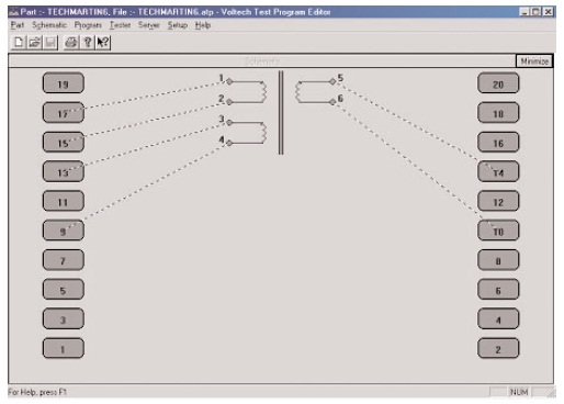
Figure 2
The picture on the right is a screen shot from the AT Editor software.
It is a graphical representation of the actual 20-node relay matrix on the AT tester itself.
Each numbered node (1-20) represents the four-relay schematic shown in Figure 1 above.
There are four relays per node and 20 nodes, totalling 80 relays.
Optimising Relay Reliability
Relays are often assumed to be an inferior alternative to solid-state switches as a switching device. However, relays offer the means to hold off thousands of volts when they are open, and they still provide a few tens of milliohms of contact resistance when they are closed—characteristics that cannot be provided by any solid-state device either now or in the foreseeable future.
The main reason relays are seen as inferior components is that they are assumed to be unreliable.
However, the mechanical life of a relay is in excess of 100,000,000 operations—enough to last more than ten years in a heavy-use transformer tester application, provided the proper technique is used for switching the relay. Voltech has developed such a technique.
In order to maximise the life of the relays, the AT3600's voltage and current sources are switched off prior to any opening and closing of the 80 high-voltage relays.
At the start of any test, the relays are closed before any voltage is ramped up.
At the end of a test, the AT3600 checks the current through the relays and, if there is still current flowing, the AT3600 will wait until this has decayed to zero before opening the relays.
This technique is known as cold switching and minimizes any arcing across the relay contacts, ensuring that the contacts undergo the minimum of degradation and thus maximising the service life of the relays and the AT3600 itself.
The importance of measuring the current for cold switching is illustrated in Figure 3 below.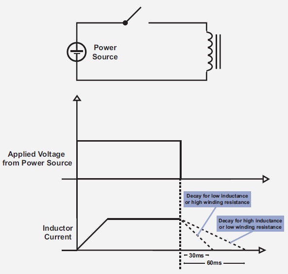
If relays are opened a fixed time after turning off the supply, then this would have to be a long time to cope with the worst-case component, unnecessarily wasting test time for the majority of components.
On the other hand, if the time chosen is too short, relays will be subject to breaking current, causing arcing and degrading their lifetime.
Most transformer tester solutions using an external matrix simply use a fixed time to determine when to open relays, with the consequent risk of relay arcing and degradation.
On its AT series of products, Voltech maximises both speed and reliability by using an integrated matrix with source and measure, an active discharge method to force the current to decay as quickly as possible, and measuring when the current falls to zero before opening.
The opening and closing action of the relays is extremely fast (approximately three milliseconds closing time and one millisecond release time).
In order to maintain the operating accuracy of the AT3600, a very comprehensive self-test routine has been incorporated into the AT5600.
The self-test sequence is user-initiated after the power-up sequence has completed. Self test has been designed to fully test the product's range of operation, including the contact resistance of its 40 source and 40 measure relays.
Contact resistance may increase over many months' usage due to molecule-thick impurities migrating to the contact surface.
If a contact resistance greater than a per-determined value is detected on a relay contact, a unique electronic cleaning process is automatically deployed until the relay contact achieves its original low value. This action further maximises the life cycle of the relays.
Conclusions
Each of the AT3600's 80 relays has an average, field-proven mean time between failures (MTBF) in excess of 100,000,000 operations, a high-voltage stand-off rating of 10 kV DC or peak AC, and a switching current of up to 3 Amps DC or peak AC.
Coupling this with the built-in self-test sequence, the relay switching speeds, Kelvin measurement system, actual switching methods, and the AT3600's unique electronic relay cleaning process makes it one of the most accurate and reliable methods of transformer fixturing and testing available in one instrument.
Notice
The arrangement of multiple relays, signal sources and measuring circuits used in Voltech AT series testers is protected by the following patents:
U.S.A.: US5500598; U.K.: 2261957B; Europe: 0621953B.