Testing Chokes and Transformers with High-Current DC Bias
A document covering DC BIAS testing using several different techniques
1, Considerations For Accurate High Power Inductor Testing
Inductors play an important part in all kinds of power electronics equipment.
They are crucial components that must perform satisfactorily over a wide range of operating conditions, for example providing energy storage as part of a power supply smoothing filter circuit from minimum to maximum rated dc current output.
It is thus important to check the dc current carrying ability of the choke at maximum current to ensure that it has been manufactured correctly, using the correct cores and wire.
For low power applications, wound components may be checked using an LCR meter only. Typical tests will be inductance (L) and quality factor (Q)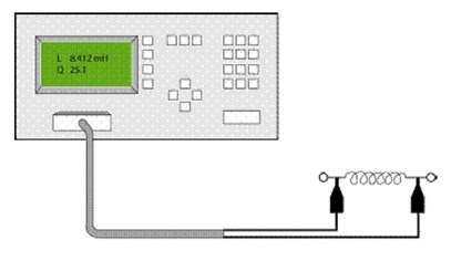
Testing Low-Power Inductors with an LCR Meter.
2, The Effect of DC Bias on Inductance Measurements
As an inductor is magnetized with a DC current or high level of AC current the inductor core will eventually saturate.
As current increases the value of inductance will reduce up to saturation to the saturation point when the inductance tends towards zero.
This is particularly evident with applications such as power supplies, power amplifiers and EMC/EMI filters, the inductance value may be significantly modified as current increases and the inductor is used closer to magnetic saturation.
The magnetic design of a coil/choke must ensure that there is sufficient flux density design margin to avoid saturation with DC bias being applied. The following B-H (B = flux density, H = magnetic field strength) curve demonstrates this characteristic: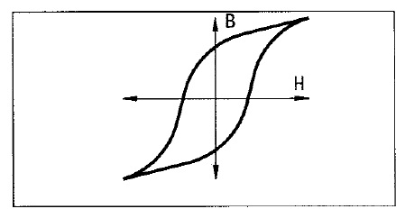
Magnetization Characteristic of Magnetic Material The "B-H Curve"
If a high power inductor is not tested as it will be used in a final application (under full load) then at best the inductor may cause system level performance issues including output noise, inefficiency and possible overheating or at worst complete failure at final test.
This is because a measured inductance is only accurate under realistic DC load conditions.
Thorough testing of an inductor under realistic load conditions may also lead to a better optimized and possibly lower cost inductor design.
3, Applying DC Bias Current During an LCR Test
A conventional constant voltage power supply cannot be used with an LCR meter because its large output capacitance will swamp the inductive impedance of the device under test (DUT) and result in 100% measurement error.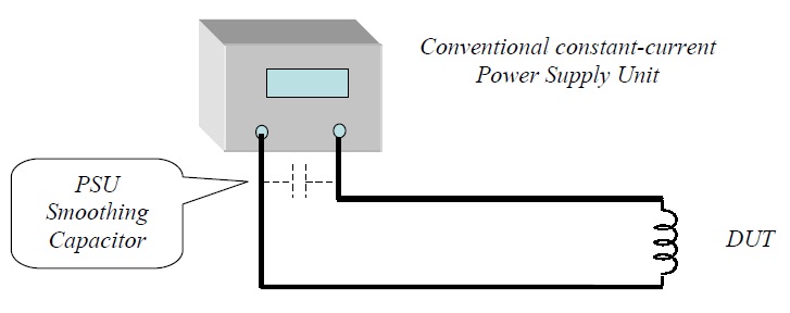
To overcome the problem of low power supply output impedance a large inductor (relative to the inductor being measured) may be inserted in series with the dc power supply in an attempt to isolate the DUT inductor from the DC power supply.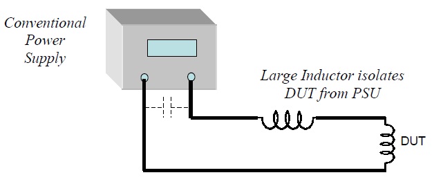
Historically this is the technique most often used by LCR meter manufacturers when they design a DC bias supply. However, the series inductor value may be very large and its self capacitance is likely to seriously affect the measurement. Also this large inductor value will have to be changed when measuring different inductor values, preventing an easily deployed solution.
4, The Modern Way to Apply DC Bias
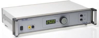
The Voltech DC1000 DC Bias Supply has a unique constant current output stage configuration which electronically (as opposed to passively) isolates the bias supply from the DUT, enabling the DUT to be tested under realistic circuit conditions with high and variable DC current.
The Voltech DC1000 electronic DC Bias supply has significantly less effect on the LCR meter measurements than conventional inductor based supplies.
The DC1000 can thus provide more accurate measurements in a smaller, lighter and more versatile and controllable package.
Read more about the theory behind our solution - DC1000 - How It Works
5, DC1000 Test Configuration With an LCR Meter
Inductance characterization may be performed manually.
We also have free Sweep Control Software for certain LCR models to control both LCR and DC1000
For manual testing current is adjusted via the front panel control knob. Inductance measurements are then read from the LCR meter as normal in real time. A spreadsheet may be used to compile of the DC current vs inductance characteristic. From this data a saturation plot can be made.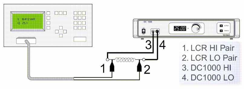
Manual test configuration
- Connect the DC1000 to the inductor DUT
- Connect the LCR meter to the inductor DUT
- Setup the LCR meter as normal. Compensate the measurement with the DC1000 output ON but delivering 0.00 Amps.
- Adjust the DC1000 via the front panel control knob for the required current step and measure inductance value (Ls) on the LCR meter.
- Compile a spread sheet and graph of current vs inductance to observe inductance variation and eventual saturation.
- Reduce the DC1000 output to 0.00 and switch the output OFF.
- Disconnect the LCR meter.
- Disconnect the DC1000.
From these results the users can see when the inductance value reduces at higher current and determine the design margin available. With the precise and easy-to-use DC1000 it is possible to speed up the design process and avoid designing with large margins, often reducing the core size required.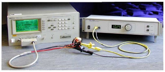
The Voltech DC1000:
- Works with most LCR meters.
- 25 A of smooth, easy-to-control dc current output.
- Stackable in parallel to 250 Amps
- Minimum effect on the LCR measurement up to 3 MHz providing accurate inductance, permitting superior accuracy LCR measurements.
6, Automatic (Production) Test Configuration
The DC1000 fits seamlessly into the Voltech AT5600, ATi or AT3600 test environment providing all the benefits that Voltech AT automated wound component testing provides.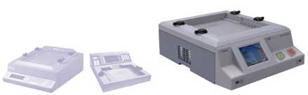
High-speed automatic testing with the Voltech DC1000 and AT series testers
- Automatic wound component tester
- 20 nodes switched automatically
- Simple programming
- > 10 DIFFERENT TESTS per second
- 40+ tests available including L, C, R, Turns Ratio, Leakage L, Return Loss, Balance, Insulation Resistance, Hi Pot (5kV), Surge, Watts, Magnetizing current.
- DC Bias current up to 500A (20 x DC1000)