
cooper CTX16-15954
Worked Example of Suitable Tests
cooper CTX16-15954
Eaton manufacture a range of PFC inductors for the active method in their CTX range.
Here we will demonstrate a possible AT test solution for their part # CTX16-15954

Transformer schema
The transformer is shown here, converted into an AT EDITOR test program schematic.
It is important to note that the windings on pins 1-4 and 2-5 are actually physically terminated independently, and thus are represented and tested as separate windings.
A Voltech DC1000 was also connected to pins 2-5 and controlled by the AT test program as the part also requires its inductance testing under 3.1 Amps DC Bias current

AT Editor Schematic for PFCs
The conventional 5mm pin terminations make the CTX16-15954 ideal for fixturing using Kelvin pins.
This gives a very quick piece-fit time, and the advantage of 4 wire Kelvin measurements for accurate resistance measurements, as all effects due to fixture wiring and contact resistance can be compensated out of measurements.


The test program first checks the DC resistance of each winding individually to check for continuity, and also as a check of correct wire gauge.
Next the Turns ratio is checked. As there are 3 windings, two turns ratio tests are required to prove all windings. a) From one of the primaries to the secondary, and b) from one primary to one secondary.
Then the series inductance is measured to check the operation of the core material, and then (using the DC1000), 3.1A DC is applied as per the spec, and the inductance is checked to prove that the core has not saturated.
Finally, the isolation is proved by a Hi Pot test between both the primaries and the secondary winding.
|
# |
Test |
Description |
Pins and Conditions |
Reason |
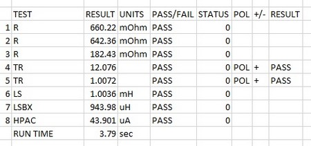
| 1 | R | DC resistance | Pins 1-4, limit set to < 0.760 Ohms, as published spec of 0.380 Ohms is for both windings in parallel. | To check the winding resistance is below a maximum. Also acts as a check of correct wire gauge and good termination. |
| 2 | R | DC resistance | Pins 2-5, limit set to < 0.760 Ohms as published spec of 0.380 Ohms is for both windings in parallel. | To check the winding resistance is below a maximum. Also acts as a check of correct wire gauge and good termination. |
| 3 | R | DC resistance | Pins 9-7, limit set to < 0.212 Ohms, as per spec. | To check the winding resistance is below a maximum. Also acts as a check of correct wire gauge and good termination. |
| 4 | TR | Turns Ratio | Energize pins 1:4 100mV 10 kHz, measure 1-4 to 7-9 to be 1:0.082 +/- 3% | To check correct turn ratio P1:S1 |
| 5 | TR | Turns Ratio | Energize pins 1:4 100mV 10 kHz, measure 1-4 to 2-5 to be 1:1 +/- 3% | To check correct turn ratio P1:P2 |
| 6 | LS | Series Inductance | Pins 1-4. 100mV, 10 kHz, limits 0.9 mH to 1.1 mH as per datasheet spec. | To check the correct number of turns and correct operation of the core material |
| 7 | LSBX | Series Inductance with DC Bias | Pins 2-5, 100mV, 10 kHz with 3.1 A DC bias applied as per part specification. Limits set to 0.75 mH minimum | Checks that cores does not saturate in presence of 3.1 A DC bias. |
| 8 | HPAC | Hi Pot AC | 1500 V for 1 second, pins 1,2,4,5 LO to pins 7,9,Hi. Limit 20 mA | Check isolation of transformer. Note that the pins with the DC1000 connected are kept on the LO side of the hi pot test. |
| AT5600 Run time 3.79 sec | ||||
| (AT3600 Run time 5.84 sec) |
NOTES:
As the LSBX (testing the part under the presence of 3.1 A DC) result is largely dependent on core material, users may prefer to execute this test periodically, rather than on every transformer to save time. The AUDIT test feature of the AT5600 will allow you test (and still retain test results) for a chosen sample of the batch.
Similarly, the HPAC testing shown matches the declared specification. Again, customers may wish to use the AUDIT function to periodically test HPAC for a longer dwell time.
Thank you for subscribing!
You’ll receive a confirmation email shortly.