Testing Laminate Transformers
A document covering Laminate Transformers and methods for accurate testing
1, Introduction to Testing Laminate Transformers
Laminate transformers are mostly used as line frequency, low frequency and low/high voltage step-up, step-down transformers.
Two coils are wound over a core such that they are magnetically coupled.
The two coils are known as the primary and the secondary.
The core material tends to be constructed from thin sheets of a soft magnetic material (approx. 0.35 mm thick), usually made of 4% silicon steel, called laminations, these are insulated from each other by varnish.
These thin sheets reduce eddy currents by increasing the resistance to the flow of such currents.
The core is partially assembled prior to the windings being inserted and once inserted the remaining laminate sheets are then interleaved to avoid all of the joints coming into one place, the joints are then staggered similar to laying bricks.
Laminate transformers are used in most low frequency applications usually between 50Hz and 400 Hz. The primary tends to have a high inductance this allows low frequency use with minimal core losses.
Laminate transformers provide the following: -
- High voltage step-up.
- Low voltage step-down.
- High current output.
- Isolation.
For the purpose of this document we will concentrate on a step-down laminate transformers.
By designing the number of turns in the primary and secondary windings, any desired step-up or step-down transformer can be realised.
The coupling between the primary and secondary must be 'tight' in a power transformer in order to reduce the leakage reactance, otherwise the drop in reactance will be considerable and will vary with secondary voltage and current.
Therefore laminate transformers are wound with concentric windings (the primary and secondary are wound with half the turns onto the core limb, one over the other (to give a close coupling) with intervening insulation.
2, Suitable Tests for Laminate TX's
The AT Series-testers have the ability to perform the following applicable laminate transformer tests:
R: R is the DC resistance offered by an inductor due to the resistance of the winding. The lower the resistance the more current an inductor will handle. Resistance is presented in mOhms to MOhms
VOC: Voltage open circuit, this test applies a voltage to the primary and reads the voltage induced in the secondary winding the results are presented as a secondary voltage from 100mV to 500 V with a test voltage from 1 V to 270V @ 20 Hz to 1.5 kHz. Phase is also measured as a polarity i.e. positive (in phase), negative (anti-phase).
IR: Insulation resistance tests are designed to check for poor shielding and insulation between windings. Voltage and current is measured and by dividing the voltage by the current insulation resistance measurements are presented in MOhms to GOhms with a test voltage from 100V to 7 kV @ DC.
MAGI: Magnetising current is the combination of the current required to magnetise the core and the current required to supply the losses in the core. Results are presented as a current from 1 mA to 2 A (3A peak) with a test voltage from 1 V to 270V @ 20 Hz to 1.5 K Hz.
STRW: At no load and with the secondary open circuit a transformer will still draw current this current is proportional to the core losses (eddy currents and hysteresis). Faraday's law suggests that providing the voltage and frequency is increased proportionally core loss should remain the same. Therefore if a dramatic power increase is detected it would indicate a winding fault. Results are presented in watts from 1 mW to 40 watts with a test voltage from 1 V to 270V @ 20 Hz to 1.5 kHz.
HPAC: Hi-pot AC tests are isolation safety tests, which tests the isolation between windings and between winding and core and winding to shield. Current flow is measured between each test point and is presented in mA to mA with a test voltage from 100V to 5.5 kV @ 50Hz to 1 kHz.
A typical laminate test sequence might be:
- R Resistance.
- VOC Voltage open circuit.
- MAGI Magnetising current.
- STRW Stress watts.
- IR Insulation resistance.
- HPAC High potential AC. Safety-test.
3, R (resistance) testing
The test parameters provided range from 10 kOhms to 10 MOhms, 10 kOhms is generally used for speed and will test each winding and termination for a value less than 10 kW.
Resistance is the direct current (DC) resistance offered by an inductor due to the resistance of the magnetic wire used. Resistance is the undesirable characteristic, which is the by-product of the wire or conductive material used. Resistance measurement's are generally taken across all windings and is directly linked to the design of the transformer to carry a particular amount of current within that winding. The lower the resistance the higher the current carrying capabilities of the inductor.
FIGURE 1 (Typical laminate step-down transformer layout).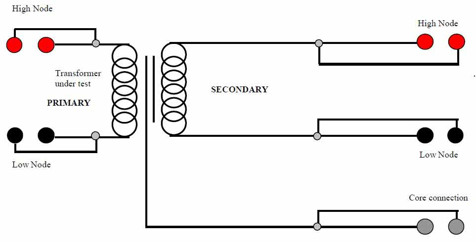
Figure 2 shows parameters required for R on the primary.
The resistance limits were chosen as a percentage of the nominal value of 100 Ohms +/- 5%.
The secondary winding would also be tested for resistance.
FIGURE 2.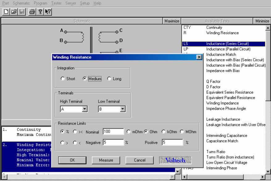
4, VOC (voltage open circuit) testing
Voltage open circuit testing is a high voltage version of the turns ratio test. Instead of returning a ratio result i.e. 2:1, 1:2 etc. a voltage result is returned that is proportional to the number of turns on the primary versus the number of turns on the secondary.
The test parameters provided range from 1 V to 270 V with a measurement range from 100 mV to 500 V. Phase is also catered for and can be selected as positive (in phase) or negative (anti-phase).
Figure 3 shows the parameters required for VOC on the primary and secondary windings of the sample transformer.
The voltage and frequency levels have been selected as U.S line frequency mains 110V @ 60Hz with the voltage limits selected as a minimum of 52 V and a maximum of 60 V. Phase has been set for a +ve.
FIGURE 3.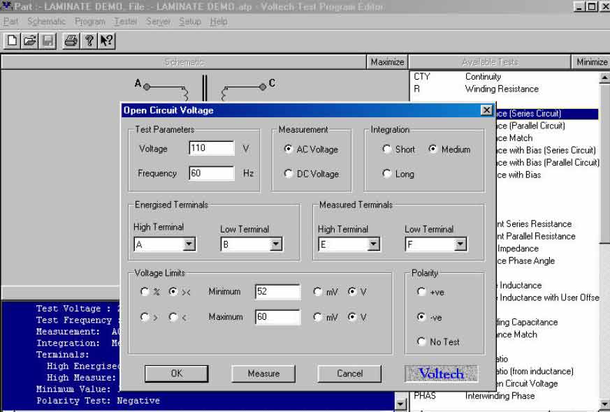
5, STRW (Stress Watts) testing
The primary role of stress watts testing is to indicate a fault in the inter-turn insulation of a winding.
This test can be used on windings with very thin wire. At no load and with the secondary open circuit a transformer will still draw current this current is proportional to the core losses (eddy currents and hysteresis). Hysteresis is the energy used up by changing the magnetic state of the core during each cycle and eddy currents are currents induced in the core by time varying fluxes.
Faraday's law suggests that providing the voltage and frequency is increased proportionally, then core loss should remain the same. Therefore if a dramatic power increase was measured it would indicate that a winding fault was present.
Stress watts testing requires a line frequency transformer of 110V @ 60Hz to be tested at 220 V @120 Hz. The core losses should not change vastly from 110V @ 60Hz to 220 V @ 120 Hz allowing double the voltage stress testing on the windings.
Figure 4 shows the parameters required for STRW on the secondary winding of the sample transformer. The voltage and frequency levels have been selected as double the induced voltage and frequency with the maximum power set at 2 watts for a dwell period of 1 second.
FIGURE 4.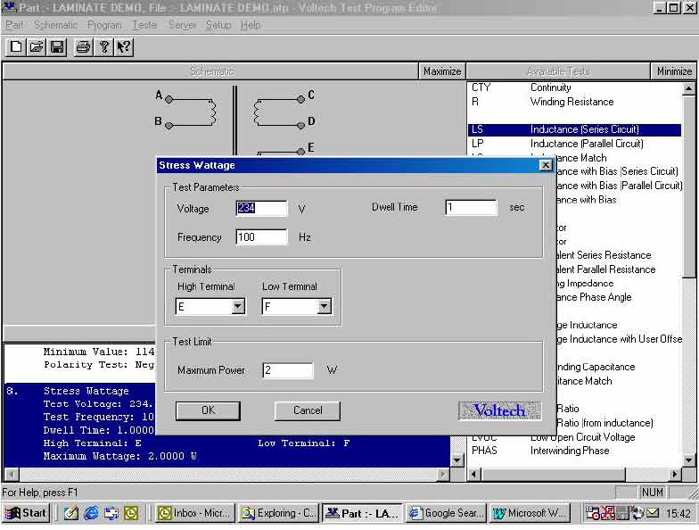
6, MAGI (magnetising current) testing
A magnetising current test is usually performed on transformers using laminate cores, which are designed to operate over the full extent of the B-H curve.
The B-H curve shows the characteristics of a magnetic material, in terms of magnetising force (H) and resulting flux density (B).
Magnetising current is the current needed to establish core flux, which results in the combination of current required to magnetise the core and current required to supply the losses in the core comprising of hysteresis and eddy currents.
Hysteresis is the energy used up by changing the magnetic state of the core during each cycle and eddy currents are currents induced in the core by time varying fluxes.
FIGURE 5: Magnetising current equivalent circuit.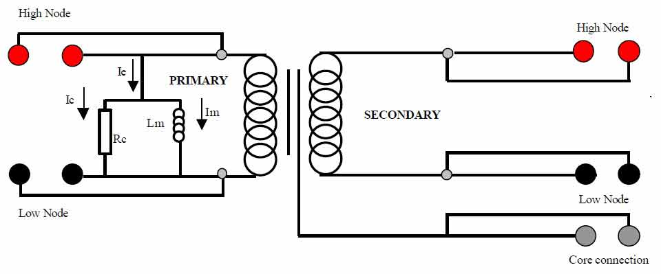
- Lm = the magnetisation inductance.
- Im = the magnetising current.
- Ie = the excitation current.
- Ic = the core loss component of the excitation current.
- Rc = the core loss resistance.
Figure 6 shows the parameters required for MAGI on the primary winding of the sample transformer.
The voltage and frequency levels have been selected for U.S line voltage and frequency (RMS) 110V @ 60Hz with the maximum current draw set at 50 mA.
FIGURE 6.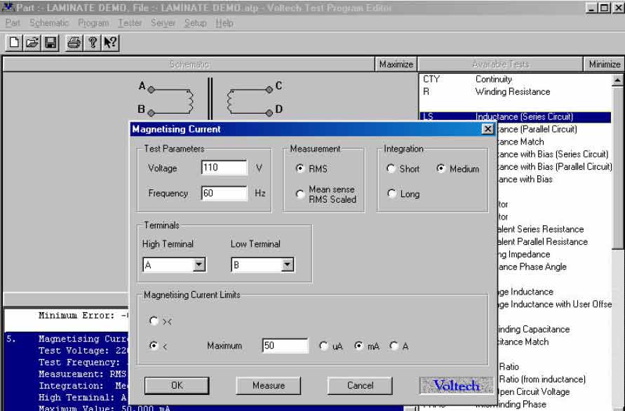
7, IR (insulation resistance) testing
Insulation resistance testing is a means of checking winding insulation and winding to core insulation.
The quality of the insulation can be checked by applying a DC voltage across the insulation and measuring its resistance.
FIGURE 7 (insulation resistance test circuit).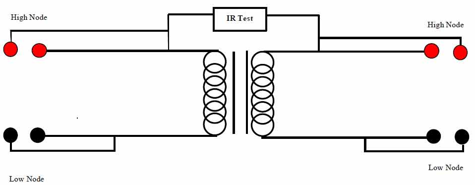
8, HPAC (high voltage safety) testing
Hi-pot or flash is a safety isolation test and is applied to isolation transformers to ensure that the isolation between the windings does not break down.
This guarantees the integrity of safety critical insulation in accordance with international standards.
Where transformers provide isolation between dangerous line voltages and safe low level voltages, HPAC is a critical test.
Multiple tests are executed between windings and between windings and the core material.
FIGURE 8 (Hi-pot AC test circuit).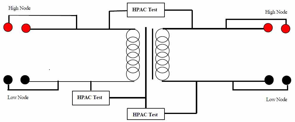
9, Complete Laminate Testing Solution
The following sample line frequency transformer specification will be used as a model to explain one method of a complete testing solution
- DC winding resistance. primary nominal value 100 Ohms +/- 5%.
- Secondary nominal value 50 W +/- 5%.
- Magnetising current 110V @ 60Hz maximum current 50 mA.
- Voltage open circuit 110V @ 60Hz minimum voltage 52 V, maximum voltage 60 V.
- Stress watts, primary voltage 220 @ 120 Hz maximum 2 watts.
- Insulation resistance @ 500 V DC, Primary to secondary 1 minimum -resistance 10 MOhms.
- Hi-pot primary to secondary 5 K V AC / 1 mA / 2 seconds.
- Hi-pot primary to core 5 kV AC / 1 mA / 2 seconds.