
Talema 62072
A worked example of testing a 120/240 Volt mains toroid using the AT5600.
Mains Toroidal transformers, as the name suggests, are used to convert mains power to lower voltages to power electronic devices.
The cores are usually made from one long strip of steel wound into a torus, with the windings then wound on top of the core.
This solid construction minimizes vibration caused by the magnetizing flux (magnetostriction), which causes transformers to hum. This provides a clear advantage over traditional laminated “E” cores.
The lack of an air gap in the design also means that Toroidal transformers emit about 8 times less stray-field interference than standard laminated core transformers, and as such are better suited for use in proximity to sensitive electronics or audio equipment.
The windings usually cover the whole area of the toroid, meaning the magnetic properties of all the core can be fully used. This results more efficient use of the core and hence a smaller device than similarly rated laminates. The low losses also result in lower magnetising current and hence further energy savings.
Talema 62072
Nuvotem Talema design and manufacture and wide range of transformers and inductors
Here we will discuss the Nuvotem Talema Part # 62072
This is a 35 VA rated Toroidal transformer designed with
Two x primaries (for 110 or 240V input), and with
Two x 12 Volt outputs (2 x 14 V open circuit, 2 x 12 V under load)

Manufacturers Schematic
The 4 windings of the # 62072 are represented on the At Editor by the schematic to the right.
As “Red” appears on both the primary and secondary, all the secondary connections are labelled with the suffix “2” for ease of identification during test programming.

At Editor Schematic
The below test results were obtained using a simple Voltech fixture with 8 quick release sockets
These allow rapid connection to the flying leads of the 62072.
The SCHUTZINGER sockets shown also have 2 independent contacts which gives true-Kelvin connections.
This int urns allows full compensation to remove the effect of the fixturing.


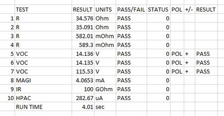
First, the DC resistance is checked on all four windings to be below the nominated maximums.
As the transformer operates at mains voltages, it is more common to test Open Circuit Voltage rather than a turn’s ratio test, as this gives a better measure of the parts operation under real voltages. As there are 4 windings we perform 3 tests to check all winding ratios as well as phase. See the link to our application note on “methods of Turns ratio measurement” at the end of this page.
The Magnetising current of the core is tested next. This test measures primary current, with the secondaries open circuited, to detect any core losses due to incorrect core assembly.
Finally, two safety tests are performed. The isolation resistance between the two primaries is checked, usually at a voltage double that seen in normal operation (here we have chosen 500 V)
This is followed by a HI POT test at 4 kV AC from all the primaries to all the secondaries.
| # | Test | Description | Pins and Conditions | Reason |
| 1 | R | DC resistance | YELLOW – BLACK | To check the winding resistance is below a maximum. Also acts as a check of correct wire gauge and good termination. |
| 2 | R | DC resistance | RED – VIOLET | To check the winding resistance is below a maximum. Also acts as a check of correct wire gauge and good termination. |
| 3 | R | DC resistance | GREEN2-RED2 | To check the winding resistance is below a maximum. Also acts as a check of correct wire gauge and good termination. |
| 4 | R | DC resistance | BROWN2-BLUE2 | To check the winding resistance is below a maximum. Also acts as a check of correct wire gauge and good termination. |
| 5 | VOC | Open Circuit Voltage | Energise primary pins YELLOW & BLACK at 50 Hz, 115 V, Measure secondary GREEN2 & RED2 and check polarity. Limits ; 14 V +/ - 5% | To check correct turns and phasing on Primary 1 to Secondary 1 |
| 6 | VOC | Open Circuit Voltage | Energise primary pins RED & VIOLET at 50 Hz, 115 V, Measure secondary BROWN2 &BLUE2 and check polarity. Limits ; 14 V +/ - 5% | To check correct turns and phasing on Primary 2 to Secondary 2 |
| 7 | VOC | Open Circuit Voltage | Energise primary pins YELLOW & BLACK at 50 Hz, 115 V, Measure primary RED and VIOLET and check polarity. Limits ; 11 5V +/ - 5% | To check correct turns and phasing on Primary 1 to Primary 2 |
| 8 | MAGI | Magnetising Current | Test voltage 110V, 50Hz. Hi terminal; YELLOW. Lo Terminal BLACK. Maximum MAGI; 10 mA | test core operation at typical operating voltage. Check that current needed to activate core is below a maximum. |
| 9 | IR | Insulation resistance | Test Voltage 500 V DC, High Terminal YELLOW and BLACK, Lo Terminal ; RED and VIOLET, Check for IR > 50 MOhms | An Insulation Resistance check is recommended as good practice for most transformers to check the integrity of the insulation between separate windings, or between a winding and a screen. In this case between the two primaries |
| 10 | HPAC | AC Hi-Pot | Test Voltage 4 kV 50 Hz, 1 second, Max I=10 ma. Pins HI; YELLOW, BLACK, RED, VIOLET. Pins LO: GREEN2, RED2, BROWN2, BLUE2. Check current is < 5mA | To check safety isolation from primary to secondaries. |
| AT5600 Run time 4.01 sec | ||||
| (AT3600 Run time 8.87 sec) |
Thank you for subscribing!
You’ll receive a confirmation email shortly.