Audio & Telecom Transformers - FAQ
Frequently asked questions about Audio and Telecommunications transformers
Audio and Telecommunications Transformer Testing - Common Questions
My audio and telecommunications transformers need to be connected to a balanced line. What test do I need to perform to ensure the necessary performance ?
What is needed here is a test for longitudinal balance, a measure of the common mode rejection ratio (CMRR) of a transformer.
This is defined as the ability of the transformer to reject unwanted noise signals that are common to both input terminals with respect to a common point.
In an ideal world, a transformer would have infinite CMRR.
However, in practice, differences in symmetry of transformer construction mean that input common mode signals appear as unwanted output voltages.
How does a longitudinal balance test work ?
Figure 1 shows a basic longitudinal balance test in which a load resister, RL is placed across the transformer output and two source resistors (RS) are placed at the transformer inputs. First the test voltage Vin is applied as a common mode signal and the output voltage Vout1 is recorded. The same Vin is then applied as a normal input voltage and the output Vout2 is recorded. Longitudinal balance is then calculated as the ratio:
LBAL = 20 log | (Vout2 / Vout1) |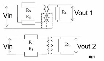
Would the standard longitudinal balance test be suitable to confirm the CMRR of audio and telecommunications transformers required to meet standards such as IEEE455 and FCC68310 ?
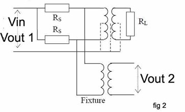
In order to assess transformers to the IEEE455, FCC 68.310 and other similar standards, a slightly different version of the basic longitudinal balance test is required. This is known as the general longitudinal balance test. In the case of IEEE455, the source and load resisters RS and RL are connected in the same way as in the previous test but a measuring (fixture) transformer is also added (see Figure 2).
A measuring transformer and load resistor are also used for testing against FCC 68.310 (Figure 3), but the source resistors are not required.
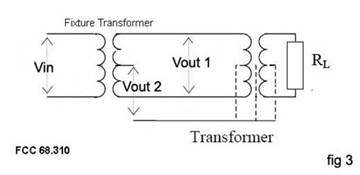
In each case, voltage Vout1 and Vout2 are measured while Vin is kept constant.
The ratio of these two voltages reflects the ability of the transformer under test to reject common mode voltages.
General longitudinal balance is calculated as the ratio:
GBAL = 20 log |(Vout2/Vout1)|
I have been told I need to conduct an insertion loss test as part of our quality process. Why is this ?
This test is often specified as it helps to ensure that the transformer has been assembled using the correct core and winding materials. Insertion los is a measure of the power that is lost by a transformer relative to the maximum theoretical power that the device should transmit to a given load. Core and winding resistance losses mean that some power is always consumed by a transformer, reducing the power available to the load from the theoretical maximum.
How do I conduct an insertion loss test ?
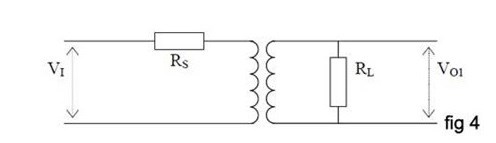
Source and load resistors (Rs and RL) are connected to the transformer under test as shown in Figure 4. The Specified voltage, Vin is then applied to the transformer and the output voltage, Vout is measured. The insertion loss (ratio of the actual to the theoretical power loss) can then be calculated using the formula:
ILOS = 10 log (Vin x Vin x Rl / 4 Vout x Vout x Rs).
A complementary measurement that may often be required at the same time as insertion loss is a test for return loss (RLOS). Unlike insertion loss where power lost within the transformer is measured, the return loss test is used to assess the power that is returned to the input by the transformer.
Are there any other tests that might be particularly applicable to audio and telecommunications transformers ?
Where transformers are to be used with transmission lines of specified impedance it will often be necessary to conductance an impedance test. The impedance of a transformer is usually complex as it consists of real (resistive) and imaginary (inductive or capacitive) elements. The total impedance at a specified frequency is the vector sum of these parts and is expressed as Z=√(R2 + X2) where R and X are the real and imaginary components respectively.
In the production environment I will need to carry out my tests at high speed – how can I automate the testing process ?
The advent of modern, single-station wound component testing systems has helped to automate and simplify the transformer testing process, while eliminating the need for OEMs to purchase, configure and maintain a variety of disparate test equipment. To date, however, many audio and telecommunications tests have not been available on such platforms. Voltech addressed this situation by launching a number of tests that are specifically designed for line isolation transformers and that can be used on the company’s ATi and AT3600 single-station transformer testers. These tests allow users to measure longitudinal and general balance in a measurement range of 0 to 100 dB, with test voltages of 1 mV to 5V and test frequencies ranging from 20 Hz to 1 MHz. Insertion losses can be measured within the same test voltage and frequency boundaries in a measurement range of -100 dB to 100 dB, while the impedance test range is 1 mOhm to 1 MOhm. Basic accuracy for these measurements is as good as 0.05%.
All of the tests can be specified with new AT5600 testers or can be purchased as simple software upgrades by existing users.
All tests can be configured and executed via PC-based transformer test editor software and test programs can be archived onto a server’s disk for rapid downloading.
Audio Testing Conclusions
The versatile AT5600 transformer tester already provides an unrivalled range of tests for checking the construction and performance of a wide range of coils and transformers. By following the above guidelines, users can also seamlessly integrate the testing of cores and transformers under constant ac current conditions into the AT3600 environment, providing high-speed PASS / FAIL testing and accurate, detailed test results for analysis.