Using the AT Series User Port
How to use the AT Series User Ports to switch your test fixture during a test for extra test coverage
1, Relay Drive Output Operation
Both the AT5600, AT3600 and ATi transformer tester possess a USER PORT connector (9-way, 'D' type, female).
This connector has been designed to facilitate an open-collector relay drive output.
The relay drive output is provided in a unique test called "OUT".
Six relay drive outputs are available to the user and can be pre-programmed via the Voltech AT Editor software to output to a number of sources or applications.
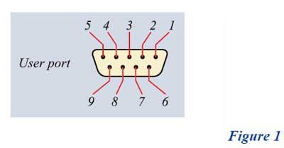
Figure 1 below shows the pin-outs available for the six relay drives:
|
Pin |
Signal name |
| 1 | O/P user relay drive 0 |
| 2 | O/P user relay drive 2 |
| 3 | O/P user relay drive 4 |
| 4 | <not used> |
| 5 | +12 V DC @ 1 Amp |
| 6 | O/P user relay drive 1 |
| 7 | O/P user relay drive 3 |
| 8 | O/P user relay drive 5 |
| 9 | <not used> |
Each relay output can drive a load of >150Ω and has a maximum current output of 80 mA.
Notes
An "OFF" state for the relay drive outputs is the default setting when the AT is switched on.
However, after each programmed "OUT" test, the relay drives will remain in the programmed condition until another "OUT" test is run, or the AT is switched off and on again.
During subsequent "OUT" tests, the AT, firstly, identifies relays that are programmed to be "OFF" and releases those relays first.
Secondly, the AT identifies relays that are programmed to be "ON" and energizes those next.
The relay switching "OFF" time is almost instantaneous. Switching "ON" times, however, are around 20 msecs.
2, Use Case - Component Switching
The most common use of the "OUT" test is to close a relay in order to introduce an additional component to the test circuit, such as a resistor, as shown in Figure 2.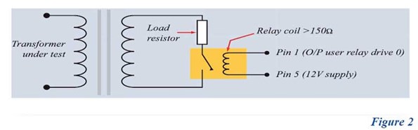
Figure 3 shows a block diagram of the relay output, which is internal to the AT.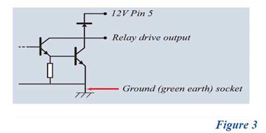
Component Switching Applications
The most common tests where the introduction of a component is required are to measure impedance mismatch between the transformer and the transmission line.
The component, in those cases, would be a resistor for tests such as GBAL (General Longitudinal Balance), LBAL (Longitudinal Balance), ILOS (Insertion Loss) and RLOS (Return Loss).
Discharging the circuit may be required where testing involves passive components such as capacitors.
These may require discharging prior to operator removal of the part under test.
3, Use Case - Triggering for An External Device
During a test sequence, an external device may require triggering.
This could be either through a relay or direct to an "ENABLE" input by using a pull-up resistor (Figure 4).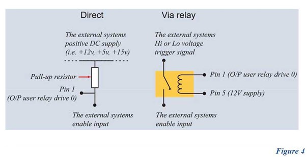
External Device Trigger Applications
- Batch counting. The trigger is sent to a digital or electrical counter in order to count the entire batch being tested.
- Conveyor belt. The trigger is sent to a timer that operates a conveyor belt, which moves passed parts along a production line.
- Robotic arm. The trigger is sent to a PC that controls a robotic arm that removes tested parts and/or places parts that are ready for test.
4, Use Case - Test Cycle Indication
During a test sequence, an LED indicator (and/or buzzer) can be used as an indication of a certain point within the program cycle being reached (Figure 5).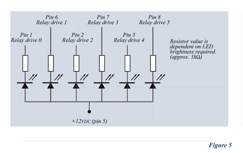
Test Cycle Indication Applications
- A timed buzzer or illuminated LED to warn the operator that the part is undergoing a hi-pot or high-voltage test.
- During multiple part testing (maximum of six - one LED per part tested), an LED can be arranged to show the test status of a particular part under test (i.e., LED illuminates when part is tested).
5, Relay Drive Set-up
The "OUT" test is accessed via the AT Editor software and can be placed anywhere in a program cycle.
The AT Editor software allows an "OUT" test to be placed anywhere in the program cycle.
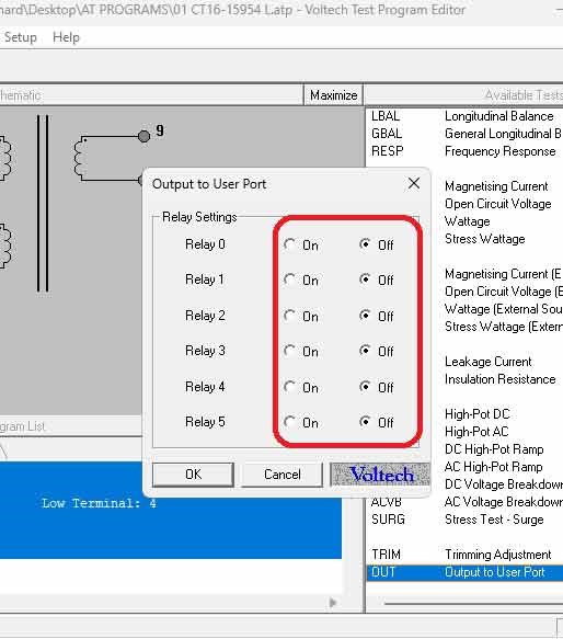
Selection of the six relay drives is easy.
Simply click the left mouse button over the ON or OFF button on any of the six drives required and click OK.
Activating a relay to add a component will require two "OUT" tests.
One to close the relay and introduce the component and another to open the relay and remove the component once the test requiring this component has finished.
Activating an enable output (and/or a program cycle indicator) would require the "OUT" test set-up in the appropriate area of the program in order to output the required event.
6, Typical Relay Specification And Recommended Cables
The list below shows the typical specification required when using relays in circuit.
However, providing that a coil rating of >150Ω is used at 12 V DC, other relays (meeting the typical specification) can be used.
Typical Relay Specification
- Switching current: 2 A maximum
- Coil resistance: 290Ω +/- 10%
- Reed switch isolation: 10 kV DC
- Coil-to-contact isolation: 10 kV DC
- Coil voltage: 12 V DC
- Contact resistance: <50 mΩ
- Voltech part number: 33-004
Recommended Cable
- Sub-miniature, screened 7/0.1 multi-core with minimum of seven cores (Farnrell part number: 711-380)