How to Detect Shorted Windings in Transformers
This document details the techniques utilized by Voltech’s AT Series testers to detect shorted windings in transformers.
Introduction: Detecting Shorted Turns in Transformer Windings
Transformers and inductors are critical components in electrical systems, comprising multiple turns of wire wound around a magnetic core made of iron, ferrite, or air. These windings are essential for efficient energy transfer. Transformers typically have multiple windings, while inductors usually consist of a single winding.


Detecting shorted turns in transformers, especially those with fine wire or numerous turns, is crucial to ensure long-term reliability. Undetected winding faults can cause increased temperatures during operation, leading to copper melting and low-resistance shorts that impair transformer functionality. The Voltech AT5600 offers advanced testing capabilities to detect such faults early in the manufacturing process, reducing the risk of in-field failures.
The Voltech AT5600 offers advanced testing capabilities to detect such faults early in the manufacturing process, reducing the risk of in-field failures.
Advanced Methods for Detecting Shorted Turns with the AT5600
The Voltech AT5600 tester utilizes two key test methods to identify shorted windings and insulation weaknesses in transformers and inductors:
SURGE or Impulse Testing (SURG) - suitable for fine wire, or high voltage windings.
STRESS WATTS testing. (STRW / STRX) - suitable for line voltage windings.
In both the following cases we will discuss the effects of stressing the primary, but remember that via basic induction of voltages across all windings, you will be testing the longevity of ALL windings on the transformer.
As such you should always stress test the winding with the greatest number of turns, as this will ensure that you are not inducing more than the generated voltage on any winding, and hence protect the UUT and AT tester.
SURGE or Impulse Testing (100 V - 5 kV DC)
As there is no universally defined method, or measurement parameter for this type of test, a perfect example component is required for comparison testing.
The perfect component will benchmark the measured result will be used as a comparison value.
The voltage level and the number of pulses required is dependent on the total amount of stress needed on the component’s winding.
As an example, in the event of a lightning trike, a mains-driven transformer could experience spikes of up to 2 kV from the raw-mains supply, therefore three pulses at a voltage level of 3 kV should adequately test and stress the windings for inter-turn insulation imperfections.
Each injected high voltage pulse will produce a defined characteristic decay time of the transient voltage.
Poor insulation and/or shorted turns will dissipate some of the energy, resulting in shorter decay times.
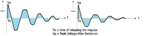
FIGURE 1 (decay versus time of one pulse from a surge test, Left=Good part, Right = Bad part).
The AT Series “SURGE” test provides a high voltage surge test from 100 V to 5 kV and a choice of 1 to 99 impulses
The test signal is generated by discharging a capacitor into the winding of the part under test, and then measuring the length of the resonant relationship between the capacitor (in the AT) and the inductor (UUT)
If multiple pulses are requested by the test program, then once the AT detects that the resonant pulse has reached zero, it will recharge the capacitor, and discharge again, for the next pulse.
This takes around 100-200 ms between the end of one pulse decay, and the beginning of the next pulse decay
There is no user-defined time parameter for the impulse and subsequent measurement, as the decay rate is dependent on the relationship between the AT Surge generator and the part under test.
The results returned by the AT are presented as a volt-second measurement (ie the area under the decay graph).
If the transformer is faulty the measured result will be a smaller value than that of the perfect transformer, as losses will cause a shorter decay time, and result in a smaller area under the graph.
The SURGE method is preferable over the later STRESS WATT method, as the higher stress voltages available give better sensitivity to a single adjacent winding failure.
Of course, use of SURGE also requires that the design of the part can withstand such high pulses even when correctly manufactured.
SURGE Test Summary
When using this test as a characterizing metric of a transformer design, parts likely to suffer an early failure can be detected by assessing the length of resonance against that of the perfect reference part used to define the limits of the test.
Any parts with hard interwinding shorts, or weak areas (for example in the enamel coating) will flash over under the stress of the voltage pulse, and so can be detected and removed from production for rework or scrapping.
STRESS WATTS testing (1-270 V AC)
A transformer will still draw some current and consume power when testing a transformer at no load with the secondary open circuit.
This power consumption is measured in watts and is the power absorbed by a coil subjected to an alternating current.
Typically, the current draw due to core loss (eddy currents and hysteresis) is only a few percent of the normal load hence is usually negligible.
Watts testing (WATT) is usually operated at the transformers full line voltage and operating frequency.
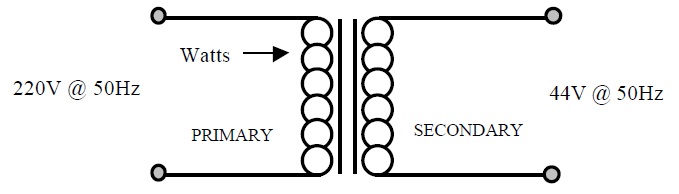
FIGURE 2 - WATT test primary 220 V @ 50 Hz, TR 5:1, secondary is 44 V @ 50 Hz
However, it is also very common and desirable to “stress” the transformer above its normal operating voltage to give some margin of quality assurance.
This stress testing (unlike normal WATT testing) should also be performed over an extended and fixed duration, as weaknesses may not show under instantaneous conditions.
During this stress period, any instantaneous dramatic increase in measured power would indicate that an inter-turn insulation winding fault or shorted turn was present as a larger amount of current would be consumed through the defect
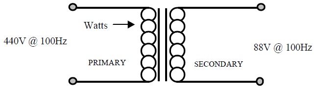
FIGURE 3 - STRESS WATT test primary 440 V @ 100 Hz, TR 5:1, secondary is 88 V @ 100 Hz
Faraday’s law shows that providing the voltage and frequency is increased proportionally core loss should remain roughly the same. Therefore, a stress watt test (STRW) can be performed at twice the voltage rating and twice the frequency rating of the transformer.
As we have proportionally increased the voltage and frequency from figure 2 to figure 3, the core loss will remain the same allowing the windings to be stressed at a greater voltage than used in normal operation.
The flux density (B) in the core will remain the same
B ~ V / (f * A * N)
N = The number of turns
A = The cross-sectional area of the core
V = Voltage applied.
f = Frequency applied
Practical notes
In reality, you will find that the core losses do increase with frequency (core losses are a function of flux density AND frequency) even though we have kept flux density the same, hence the STRW may read higher, but the result will still be repeatable and characteristic. You can mitigate the core losses by doubling the F again, so for a 100 V, 50 Hz transformer, you may find that 200 V, 200 Hz is more suitable than 110 V/100 Hz.
Line supply transformers typically have a 240V winding, with a tap to give 2 x 120 V windings.
To double the voltage on the 240V winding would require 480 V, which is beyond the 270V capacity of the STRW test.
Here we suggest either;
a) Testing the 120 V winding (if you have one) individually at 120 V (WATT) for normal operation and then at 240 V for the stress (STRW) test. This will in turn induce 480 V across the 240 V winding, without the need to supply the 480 V
or
b) Testing a lower voltage secondary, at twice its operating voltage. Similarly, this would induce 480 V on the primary, but as the primary nodes would not be used in the test, the 5 kV isolation on open test nodes will protect the AT tester.
STRW Test Summary
The AT5600 and AT3600 provide a stress watt test (STRW) from 1 V to 270 V @ 20 Hz to 1500 Hz to detect potential faults in the inter-turn insulation of a winding.
The user must also specify a dwell time for the test from 0.5 s to 180 s, over which the power is continually monitored.
The test results are presented in Watts.
Where voltage and current levels require extending, please use Voltech’s AC Interface fixture with the AT.
This allows use of either an external step up transformer, or an AC power source to generate higher voltage (up to 600 V) and current (up to 10 A)
The test signals, measurement, and pass-fail criteria are still automatically controlled by the AT using the 4 X tests; MAGX, WATX, STRX and VOCX.