
Pulse Transformers
Worked Example of Suitable Tests
Pulse transformers are a diverse family of transformers designed to transfer a digital control signal from a control circuit to a load.
They provide galvanic isolation to a circuit, whilst allowing fast control signals to be transmitted without distorting the signal shape.
The input and output signal is typically a rectangular wave of a few volts with a frequency above 100Khz, not a sinusoidal wave as with conventional transformers
Pulse transformers have a low number of windings (to minimize flux leakage) and low inter-winding capacitance (to ensure that the profile of the signal is maintained on the secondary as cleanly as possible.)
As they operate with high frequency signals, the core material must be able to cope with repeated and rapid magnetization and demagnetization.
The turns ratio is typically 1:1 as their main purpose is not to increase or transform the voltage, but to maintain it across the isolation barrier.
Pulse Transformers
A good example of a pulse transformer is the Murata 786 series of devices.
The Murata 786 series are available in a variety of winding arrangements, with or without centre taps on the windings. For the purposes of this example, we will focus on the 78601/1C, which has 1 primary and 1 secondary

78601/1C manufactures schematic
The above schematic can be easily converted into an AT Test program using the AT EDITOR software.
The simple schematic is shown here

AT Editor schematic
The 786 series of pulse transformers can be easily connected using a Kelvin pin fixture.
As the winding resistance is low, (<1 Ohm), the testing will benefit from the improved accuracy provided by 4 wire measurements.

Simple kelvin pin fixture
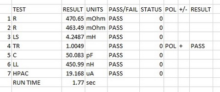
The resistances of the two coils are first checked to be below the specified maximum of 0.6 Ohms on each winding.
Next the inductance is checked to validate the core operation,
The limits here specify a minimum inductance rather than a nominal and tolerance, so only a check for greater than 2 mH is performed (although the AT will record the actual measured value anyway)
Turns ratio is checked next to check the 1:1 ratio to limits of +/- 1%.
If the actual number of turns is known, then it is best practice to use these as the nominal, with +/- 0.5 turns as the tolerance.
Inter-winding capacitance and leakage inductance are checked next, again in line with the published data.
As both these are largely governed by the design, some users may prefer to run these tests as occasional audit tests to save test time, whilst maintaining quality auditing.
Finally the Isolation is checked using a standard AC HI-POT test.
|
# |
Test |
Description |
Pins and Conditions |
Reason |
| 1 | R | DC resistance | Pins 1-3, Check < 600 mOhms | To check the winding resistance is below a maximum. Also acts as a check of correct wire gauge and good termination. |
| 2 | R | DC resistance | Pins 6-4, Check < 600 mOhms | To check the winding resistance is below a maximum. Also acts as a check of correct wire gauge and good termination. |
| 3 | LS | Series Inductance | Pins 4-6, 1 kHz, 100mV, Limits check L >2 mH | To check the correct number of turns and correct operation of the core material |
| 4 | TR | Turns Ratio | Energise primary pins 1&3 at 1 kHz, 100mV, secondary 4&6, check for 1:1 ratio, +/- 1%, Positive polarity. | To check correct turns and phasing on Primary to Secondary |
| 5 | C | Inter-winding Capacitance | 5V, 100 kHz, Pins 1&3 Hi, Pins 4&6 Lo, limits 49 pF+/-10% | The capacitance is usually a function of the design of the winding positioning and topology, so is usually set by the design. However, you may occasionally wish to audit this during manufacture. |
| 6 | LL | Leakage Inductance | 50 mA, 300 kHz Pins 1-3 with 6-4 shorted, limits ; better than 470 nH | Checks that coupling between winding does not result in excessive loss of magnetic flux transfer |
| 7 | HPAC | AC Hi-Pot | 1 kV 50 Hz AC, 1 second, Pins 1&6 High, Pins 2,3,4 & 5 Lo. Check current <1 mA | To check isolation from primary to secondaries. |
| AT5600 Run time 1.77 sec | ||||
| (AT3600 Run time 3.68 sec) |
NOTE:
Many pulse transformers also define a “Volt time product” to define the energy capacity of the transformer.
This is effectively already checked in the above test scheme, as the factors affecting this are
a) the core, the core area and the saturation flux density of the core material (checked by the inductance test)
b) the number of turns (checked by the TR test)
Thank you for subscribing!
You’ll receive a confirmation email shortly.