
Wurth Electronics part #7491199212
Worked Example of Suitable Tests
In recent years, the emergence of “The Internet of Things” has lead to a massive rise in the number of devices connected to the Internet via Ethernet cabling.
Historically each of these devices also has a separate power supply to provide the local 5 or 12 voltage required to drive them
One rapidly emerging solution for this is Power Over Ethernet (or PoE for short).
There are two basic versions of PoE.
One version supplies the voltage on the Data Transmit and Receive pairs (TX and RX); i.e. combines the power and data.
The second version supplies the power on unused pairs of the cable
The first method is preferred for simplicity and also has the advantage of backward compatibility with existing wiring.
The advantages of such a system are many
- Firstly the power is regulated and isolated at one central point.
- Secondly the installation of PoE devices is simpler as only reliant on one cabling system.
- Thirdly, any interruptions to the power supply can be handled by one central UPS system,
- Fourthly, the design of the devices can be mechanically and electrically simpler, as they require only one external port to the outside world.
Furthermore, newly designed equipment can be designed with the transformers and circuitry needed to split the digital data and power signals in the device, and legacy equipment can still be used by employing a local “splitter” box, (similar in concept to ASDL splitters).
In all cases transformers are used to isolate the device and separate the signals.
Wurth Electronics part #7491199212
Wurth manufacture an extensive range of transformers for PoE applications.
Here we will examine the Wurth Electronics part #7491199212.
This is a four winding transformer with turn ratios of ;
N1 : N2 : N3 : N4
1.00 : 0.29 : 0.29 : 0.21
It comes in a Surface mount package.

Schematic #7491199212.
The four windings of the transformer are represented here, using the same numbering as the Wurth schematic for ease of programming.
Note that the non-sequential pin numbering has been kept here for ease of programming, and also to keep the polarity convention used on the original schematic.

AT Editor schematic
The transformer package is a standard surface mount design, and as such not suitable for Kelvin pins.
The fixturing shown here is a zero insertion force socket (ZIF) in which pairs of blades are closed onto each pin from the side.
This has the advantage of not putting the part under any mechanical strain whilst still maintaining a true Kelvin contact to each winding.

ZIF (zero insertion force) socket fixture

ZIF (zero insertion force) socket fixture
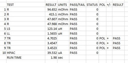
| # | Test | Description | Pins and Conditions | Reason |
| 1 | R | DC resistance | pin 1-2, limits <110 mOhms | To check the auxiliary winding resistance is below a maximum. Also acts as a check of correct wire gauge and good termination. |
| 2 | R | DC resistance | pin 3-4, limits <450 mOhms | To check the primary winding resistance is below a maximum. Also acts as a check of correct wire gauge and good termination. |
| 3 | R | DC resistance | pin 9-8, limits <100 mOhms | To check the first secondary winding resistance is below a maximum. Also acts as a check of correct wire gauge and good termination. |
| 4 | R | DC resistance | pin 7-10, limits <100 mOhms | To check the second secondary winding resistance is below a maximum. Also acts as a check of correct wire gauge and good termination. |
| 5 | LS | Series Inductance | Pin 3-4, 100mV, 100 KHz, nominal 127 mH +/- 10% (as per published spec) | To check the correct number of turns and correct operation of the core material |
| 6 | LL | Leakage Inductance | Pins 3 -4 Hi, Pins 8-9 Low, 100mV, 100 kHz , check below 2.3 uH as per spec. | To check leakage is below specified limit as a validation of correct placement and operation of windings. |
| 7 | TR | Turns Ratio | Energise pins 3-4, 100 mV, 100 kHz, check Turns ratio and phase 3-4:2-1 to be 1:0.21 +/- 3% | To check correct ratio of windings |
| 8 | TR | Turns Ratio | Energise pins 3-4, 100 mV 100 kHz, check Turns ratio and phase 3-4:7-10 to be 1:0.29 +/- 3% | To check correct ratio of windings |
| 9 | TR | Turns Ratio | Energise pins 3-4, 100 mV, 100 kHz, check Turns ratio and phase 3-4:8-9 to be 1:0.29 +/- 3% | To check correct ratio of windings |
| 10 | HPAC | AC Hi-Pot | 1.5 kV AC, 1 second, Pins 1,2,3,4 High, Pins 7,8,9,10 LO. Check <5 mA current | To check isolation as per datasheet. |
| AT5600 Run time 1.98 sec | ||||
| (AT3600 Run time 4.19 sec) |
Thank you for subscribing!
You’ll receive a confirmation email shortly.