
TCT40-01E07AB
Worked Example of Suitable Tests
Laminate transformers have cores composed of layers of silicon steel, so that the laminations limit the effect of loss-causing eddy currents than can build up under magnetic excitation.
They typically operate at mains or low frequencies (50-400 Hz) and higher voltages (110-240 Volts)
TCT40-01E07AB
Triad Magnetics manufacture several types of laminated core transformers
Here we will discuss the testing of the TCT40-01E07AB control transformer.

TCT40-01E07AB schematic
The transformer is easily represented using the AT EDITOR software as a two winding transformer.
Note that we have also connected the laminate core to a test node, as we will be performing hi pot tests between the windings and the cores, not just from primary winding to secondary winding.

AT Editor Schematic
The TCT40-01E07AB has 4 large tabs, two for the primary and two for the secondary.
In the picture shown left we have used a Voltech Universal Fixture (part # 91-186) to bring each test node to 2 4mm safety sockets.
We have then used Voltech's Kelvin Clip Leads (part # # 78-028) to make quick connection to the UUT, including one to the core so that core Hi-pot isolation can be checked.

AT Fixturing using 91-186 fixture and 78-028 kelvin clips
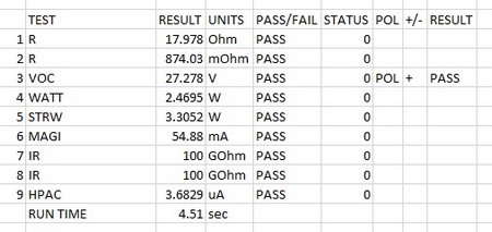
Firstly, standard resistance tests are used to check for good termination and as a check of gauge of wire.
Next, a VOC (Open circuit Voltage) test if performed to check both the winding ratio and the phase between turns. This is preferred over a conventional TR turns ratio test, as VOC can be performed at the actual running voltage of the transformer, and hence gives a result based on real life performance.
Then a WATT test is used to a measure of the input power required energizing the transformer at no load.
This is an excellent check on the magnetic quality of the iron core and the magnetic joints. The limits can be set from empirical measurements from a batch, or from design parameters.
This is followed by a Stress Wattage test (STRW). This is similar to the Watt test, except that it is run typically at double the operating voltage (so tested here at 220 V) to check for inter-winding breakdowns (e.g. weak points in the wire enamel).
Any breakdown will result in a loss of energy and hence a higher STRW reading compared to a normal transformer.
Its is best practice to also increase the frequency (here 600 Hz) as this lowers the background “good” reading, and makes and deviation due to breakdown more easy to measure and detect.
It is common and best practice to energise the primary at 2 x normal voltage for this test, however, the limit on the applied voltage from the AT is 270 volts.
Luckily, it is just as valid to run this test by energizing the secondary at twice the operating voltage (in this example 27 x 2= 54 V) as the transformer primary will still energise in line with the turns ratio and allow you to test the primary at higher than 270V if needed.
This of course applies if the transformer was multi-winding; the whole transformer is energised, so we are testing for breakdowns across the whole transformer, not just the energised winding.
Care must be taken in cases of large turns ratios, that energizing the secondary does not produce extreme voltages in excess of 5 kV
Magnetising current is measured and checked next, at 110V / 60Hz.
This test checks the action of the core, and for correct assembly of the laminations by measuring the current needed to excite the core.
Two Insulation tests are performed next, once from Primary to secondary, and once from primary to core. The test is executed at 1.5 kV DC and resistance is confirmed to be higher than 20 GOhms.
Finally HPAC is used to check isolation at 1.5 kV AC from the primary to the secondary and core combined to validate safety.
|
# |
Test |
Description |
Pins and Conditions |
Reason |
| 1 | R | DC resistance | Primary winding, check R is less than 20 Ohms | To check the winding resistance is below a maximum. Also acts as a check of correct wire gauge and good termination. |
| 2 | R | DC resistance | Secondary winding, check R is less than 1 ohm | To check the winding resistance is below a maximum. Also acts as a check of correct wire gauge and good termination. |
| 3 | VOC | Open Circuit Voltage | Energise primary at 120 V, check that secondary reads 27 V +- 5 and that polarity is +ve | To check correct turns and phasing on Primary 1 to Secondary 1 |
| 4 | WATT | Wattage | Energise primary at 120 V, 60Hz. Check that Watts <3 W | Correct core material and core properly assembled |
| 5 | STRW | Stress Wattage | Energise primary at 240V, 600 Hz for 1 second. Check that Watts <4 W | Checks integrity of inter-turn insulation, the magnetic material and joints |
| 6 | MAGI | Magnetising Current | 120 V 60 Hz applied to primary. Check Magnetising current is less than 60 mA | Correct primary turns Correct core material properly assembled |
| 7 | IR | Insulation Resistance | Check Primary to Core at 1.5 kV DC > 20 GOhms | Winding and core isolation check |
| 8 | IR | Insulation Resistance | Check Primary to Secondary at 1.5 kV DC > 20 GOhms | Winding and core isolation check |
| 9 | HPAC | AC Hi-Pot | 1.5 kV AC for 1 second from primary to Core + Secondary. Check Current < 100 uA | To check High voltage safety insulation |
| AT5600 Run time 4.51 sec | ||||
| (AT3600 Run time 8.21 sec) |
Thank you for subscribing!
You’ll receive a confirmation email shortly.