
Epcos B82731M2351A030 choke
Worked Example of Suitable Tests
Epcos B82731M2351A030 choke
If a differential mode current is present, then the two coils create equal and opposite magnetic fields which then cancel each other out.
The choke thus presents zero impedance to any differential mode signal, which passes through the choke without any attenuation.

Differential signal
In contrast, a common mode signal flows in the same direction on both lines, creating magnetic files that are in phase and do not cancel.
This will then present high impedance and hence attenuate any common mode signal.
The actual attenuation (or common mode rejection) depends on the relative magnitudes of the choke impedance and the load impedance.

Common mode signal
A good example of a classic design of common mode choke is the EPCOS series B82731, of which we will be discussing the Epcos B82731M2351A030.

B82731M2351A030 drawing and footprint
The four-pin transformer is easily represented using the AT Editor software using two windings.

AT Editor Schematic
The conventional THP pin footprint makes the part suitable for a Kelvin-pin fixture.
It will allow us to compensate out the contact resistances inherent in any fixturing before measurement.
It also offers excellent part change-over over times of the order of seconds.
The picture to the right is a Voltech Custom Fixture ordered using our Online Fixture Designer

Voltech Custom Fixture using 4 kelvin pins for CM choke

Detail - Voltech Custom Fixture using 4 kelvin pins for CM choke
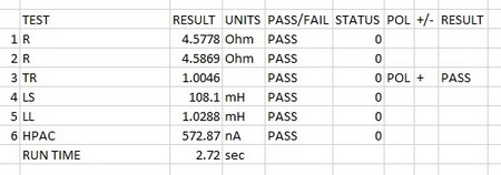
The test program first checks DC resistance on each winding, and then turns ratio is 1:1 within 2%
This is followed by two inductance tests:
1. The standard series inductance on one winding is checked to make sure its within the spec.
2. The leakage inductance (a measurement of how well the windings are coupled), which in the case of a common mode choke must be kept to a minimum)
Finally the line-to-line stand off voltage is confirmed by means of a AC Hipot test at 1500V.
|
# |
Test |
Description |
Pins and Conditions |
Reason |
| 1 | R | DC resistance | pin 1-4, limits <4.5 Ohms +- 10% as per spec | To check the winding resistance is below a maximum. Also acts as a check of correct wire gauge and good termination. |
| 2 | R | DC resistance | pin 2-3, limits <4.5 Ohms +- 10% as per spec | To check the winding resistance is below a maximum. Also acts as a check of correct wire gauge and good termination. |
| 3 | TR | Turns Ratio | Energize pins 1-4, 500mv 10khz, check Turns ratio (1-4:2-3) to be 1:1 -+ 2% | To check correct ratio of windings |
| 4 | LS | Series Inductance | Pin 2-pin 3, 100uA, 10 Khz, nominal 100mH + 50% / -30% (as per published spec) | To check the correct number of turns and correct operation of the core material |
| 5 | LL | Leakage Inductance | Pins -4 Hi, Pins 2-3 Low, 5mA, 10kHz , check below 1.05mH | To check leakage inductance is below specified limit. |
| 6 | HPAC | AC Hi-Pot | 1kV AC, 1 second, Pins 1&4 High, Pins 2,3 Lo | To check isolation as per datasheet. |
| AT5600 Run time 2.72 sec | ||||
| (AT3600 Run time 5.21 sec) |
NOTE:
The data sheet also specifies curves for Impedance (Z) response over frequency.
This is not usually tested in a production environment as it is embodied in the design choice of cores and windings. If you wish, the AT’s “Z” test could be used here periodically, by using the AUDIT function to occasionally validate this performance on 1 in 100 transformers.
Thank you for subscribing!
You’ll receive a confirmation email shortly.