
Hammond Manufacturing CT
Worked Example of Suitable Tests
Current transformers are widely used in the industrial measurement sector to enable the monitoring of high currents using standard meters.They are used to enable the measurement of very high currents.
Current transformers provide two functions; firstly to step down a very high current that needs to be measured, to a lower current level suitable for cheaper and easily available ammeters.In doing this they also provide the secondary function of isolating the measurement equipment (and the user) from the very high currents to be measured.
They are typically supplied in a number of different winding ratios, such that the user can select a suitable model to transform the current down to a 0-5A signal for measurement. Additionally different models are rated in terms of “Burden”, which is usually expressed as the apparent power in VA at the coils maximum operating current.
The CT series from Hammond Manufacturing are good examples of this type of transformer.
Here we will test the part CT100A, designed for measuring up to 100 Amps
Hammond Manufacturing CT
The AT Editor Schematic is shown here.
T1 and T2 represent the “test coil” (10 turns) that we will use, and HI and LO represent the Current Transformer under test.
Current transformers, in real world use, operate by being placed around one single conductor carrying the current to be measured.
This acts as the primary, and the CT itself is the secondary.
To obtain more accurate results in a test situation it is suggested to use a quick-detach coil as a test “primary” to simulate the current conductor being measured by the CT, and to also make this primary a multiple turn (in our example 10 turns) to allow more accurate readings of the “secondary” (CT coil).
In our example the CT itself has 20 windings, (100A:5A in normal “single conductor” use) and our test coil has 10 windings, so we expect the turns ratio under test conditions to be 2:1.

To keep your connection time to a minimum, we suggest using a quick release lead, for example, using the Omnetics Nano connector for the test primary coil (T1 and T2)
https://www.omnetics.com/products/micro-and-nano-circulars/cots-micro-360-and-nano-360
A22004-001 (Male 12 way) and A22005-001 (Female 11 way)


First the resistance of both the test coil and the CT it self are checked to confirm correct functioning of the test coil, and to validate the CT wiring.
Next The Inductance is checked on the coil, as this confirms the core material and winding.
The LS test usually gives a good validation of number of turns and core performance
However, the large tolerances on the AL value (usually +/- 30%) on the toroid cores used on most CTs can make this a poor detection method of incorrect turns, especially in a measurement application where one too few or many turns will drastically affect performance.
As such it is still recommended to perform a turns ratio test with tolerances of +/- 0.5 turn to ensure the exact number of windings.
|
# |
Test |
Description |
Pins and Conditions |
Reason |
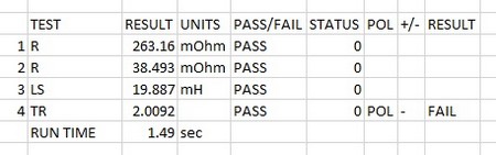
| 1 | R | DC resistance | Pins T2-T2, Check < 300 mOhms | To check the winding resistance on the test coil to correct connection of the test coil. |
| 2 | R | DC resistance | Pins HI-LO, check < 40 mOhms | To check the winding resistance of the current transformer is below a maximum. Also acts as a check of correct wire gauge and good termination. |
| 3 | LS | Series Inductance | Test pins HI-LO, 50 Hz, 1 V, 20 mH +/ - 10% | To check the correct number of turns and correct operation of the core material |
| 4 | TR | Turns Ratio | Energise primary HI and LO at 50 Hz, 100mV, secondary T1 and T2, Ratio 20:10 turns + /- 0.5 turn. | To check correct turns and phasing on Current transformer. It is always best practice to energise the winding with the most turns for most accurate results. |
| AT5600 Run time 1.49 sec | ||||
| (AT3600 Run time 1.50 sec) |
Thank you for subscribing!
You’ll receive a confirmation email shortly.