Measuring Leakage Inductance in Transformers
An explanation of Leakage Inductance in transformers, why it is important, and how to best perform measurements
What Is Leakage Inductance?
Leakage Inductance is a critical inductive component in transformers caused by imperfect magnetic coupling between windings.
This results in magnetic flux that does not link the primary winding to the secondary winding, acting as inductive impedance in series with the primary. Accurate measurement of leakage inductance is crucial in applications such as switched-mode power supplies and lighting ballasts, making it a key testing function for transformer manufacturers.
Ideal Transformer vs Real Transformers
Ideal Transformers
In a theoretical perspective, an ideal transformer exhibits no losses, with voltage transformations occurring in direct proportion to turns, while currents transform inversely.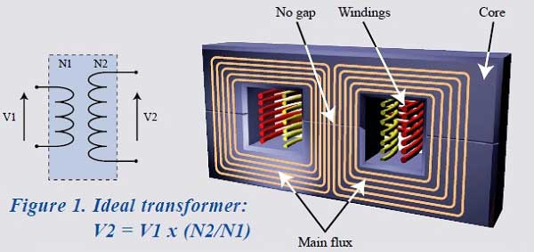
Real Transformers
In a real transformer, some of the flux in the primary may not link the secondary winding.
This "leakage" flux does not contribute to transformer action and adds inductive impedance in series with the primary winding.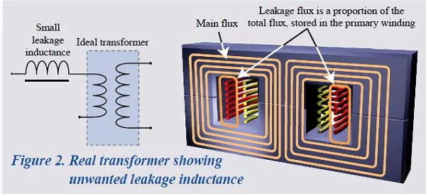
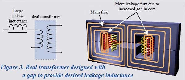
Impact of Air Gaps in Transformers
In certain transformer designs, leakage inductance must be a greater proportion of the total inductance and is specified within a tight tolerance.
The increased proportion of leakage inductance is usually achieved by introducing an air gap in the core design, thus reducing the permeability of the core and therefore the value of primary inductance.
The ratio of flux that does not link the primary winding to the secondary winding will therefore increase relative to the flux that links both windings.
Importance of Measuring Leakage Inductance
Leakage inductance (LL) can be undesirable in a wound component, in which case it is important to measure the value to show that it is low or, in some applications, such as electronic lighting ballasts and resonant power converters, leakage inductance is deliberately introduced and its value is an integral part of the circuit design.
In these applications, the leakage inductance provides an energy storage medium that is essential to achieve correct operation of the finished product.
It is therefore important that the value of leakage inductance of the transformer is known to be within specified limits.


Measuring Leakage Inductance
To measure Leakage Inductance, an LCR meter is connected to the primary winding of a transformer with the secondary terminals left open. 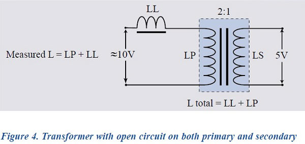
Where:
L = Inductance Value
LP = Primary Inductance
LL = Leakage Inductance
Since LL is a function within the transformer, it is clearly not possible to measure its value directly.
A method must therefore be used to subtract the value of LP from the total measured inductance.
This is achieved by applying a short circuit across the secondary terminals.

A perfect short circuit will result in zero volts on the output terminals and, through transformer action, zero volts will also appear across the primary inductance. The measured value of inductance at the primary terminals will therefore be the true leakage inductance (LL).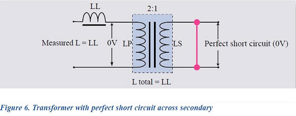
Measurement Challenges
Unfortunately, achieving a perfect short circuit on the secondary of a transformer is difficult in a laboratory and completely impractical in a production environment.
In a production setup, it is common for the short circuit to be applied manually or via a switchable relay.
Under these conditions, a perfect short circuit cannot be achieved, and it follows that the secondary voltage will not be truly zero.
The voltage attributable to the imperfect short circuit will then appear across the primary inductance as a short-circuit error multiplied by the turns ratio.
Ls/c is reflected in the primary as N2Ls/c because, in any winding, L is proportional to the number of turns squared (L α N2).
Thus, Ls/c is reflected as a function of: ( Np / Ns ) ^ 2 = ( Lp / Ls )
The measured value of the primary inductance can be considered vectorially as the sum of the leakage impedance plus the reflected impedance of the short-circuit error. This is shown in figure 8.
Traditional Measurement Method
In order to obtain the true value of leakage inductance, engineers will carefully apply a soldered short circuit to the secondary of the transformer to be tested and measure the value of inductance on the primary.
This value of inductance will be recorded as the 'true' leakage inductance (e.g. 150μH).
The inductance will then be measured on the same transformer after the soldered short circuit has been replaced by either a shorting clip or a fixture with relay-operated short circuit, depending on the technique that will be chosen for production.
The measured inductance is again recorded (e.g. 180μH).
This value will, of course, be greater than the original because it includes the true leakage inductance plus the short-circuit error inductance.
The difference between these two values (in our example 30μH) is then used in production testing as a fixed offset that is programmed into a production LCR meter to obtain an approximation of the correct value in the presence of an imperfect short circuit.
In practice, it is impossible to achieve a relay-based or manual-based short circuit that produces exactly the same short-circuit error every time.
This non-repeatability of short-circuit error is such that the fixed offset cannot provide a production department with accurate and repeatable results.
This is illustrated in the following table:
|
True LL |
Meas. value |
Fixed offset |
Result |
Pass/fail |
|
| Meas. #1 | 150 μH | 180 μH | -30μH | 150 μH | ✓ |
| Meas. #2 | 150 μH | 200 μH | -30μH | 170 μH | X |
| Meas. #3 | 150 μH | 250 μH | -30μH | 17 5μH | X |
Voltech's Solution for Measuring Leakage Inductance
Voltech have developed the AT series testers with an architecture and processing ability to remove the short-circuit error from the primary inductance measurement during each and every test.
Firstly, as part of the LL test, a silent measurement is made of the Turns ratio of the part under test. This is performed at approximately 1 Volt and at the same frequency as the programed LL test.

The Voltage on the secondary is also measured when the secondary is open circuit. This gives us Vopen on the above graph.
Second, With the (non ideal) short applied to the secondary, the voltage and current are also measured.
This gives us the point V1/I1 on the graph.
These two points are then extrapolated (on the assumed linear V/I line) an calculated back to where V=0 to give Ishort. This is the expected current flow in the secondary under the Ideal short condition - i.e. where the short is perfect and there is no voltage drop across the secondary.
This Ishort value combined with the earlier silent TR result can be used to calculate the corresponding current effect on the primary side, and hence removed from the LL result measured on the primary.
This is a simplified version of the technique. In reality, the measurements are a combination of real and imaginary measurements, so the technique is shown vectorially below:

From the primary vector diagram, it can be seen that each measurement is the sum of the voltage attributable to the leakage inductance plus the error voltage from the secondary short circuit.
Before applying a short circuit, the Voltech AT series testers measure the primary to secondary turns ratio.
The testers then automatically apply a short circuit, using an internal relay matrix, and measure the short-circuit voltage at the transformer secondary pins.
The vector of this short circuit voltage is automatically multiplied by the turns ratio, producing an 'error vector' that is equal to the short-circuit error voltage reflected into the primary measurement.
The leakage inductance is then computed from the total primary inductance value less the primary error vector that has been calculated.
This process enables Voltech AT series testers to provide the true leakage inductance value, irrespective of short circuit variability.
|
True LL |
Measured value |
Real-time vector comp. |
Result |
Pass/fail |
|
| Meas. #1 | 150 μH | 180 μH | ✓ | 150 μH | ✓ |
| Meas. #2 | 150 μH | 200 μH | ✓ | 150 μH | ✓ |
| Meas. #3 | 150 μH | 250 μH | ✓ | 150 μH | ✓ |
Conclusion
Leakage inductance is a critical transformer characteristic that presents a particular measurement challenge to both design and production test engineers.
By looking at the factors effecting measurement integrity and developing innovative measurement techniques to overcome these factors, Voltech provides a unique solution to a problem of measurement variability that faces almost all transformer manufacturers.
Should you have questions on any of the other test functions available for the Voltech AT series transformer testers, please do not hesitate to contact us.