DESIGN YOUR CUSTOM VOLTECH SURFACE MOUNT DEVICE TEST FIXTURE
IMPORTANT: This fixture accommodates
J-wing
and Gull-wing
lead types that extend outward from the body of the transformer.
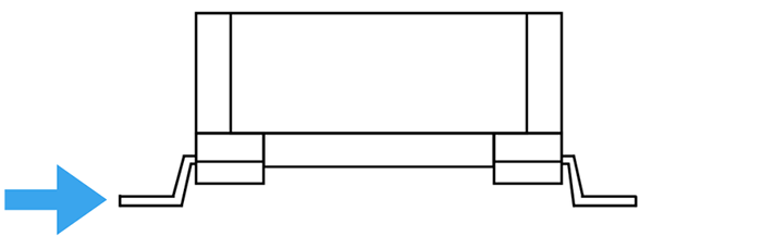
(SIDE VIEW)
TRANSFORMER DIMENSIONS SPECIFICATION
Note: Use the fields below to enter your transformer dimensions according to your specifications or datasheet. Values that are invalid or outside the acceptable range will cause the corresponding input field to display in RED.
Tip: Verify the actual dimensions of your surface-mount devices with high-precision calipers, rather than relying solely on specifications or datasheet land pattern data, to ensure proper fit and alignment.
CUSTOMIZE WIRING CONFIGURATION
DEFINE HOW EACH TRANSFORMER PIN CONNECTS TO THE AT NODES
SELECT A WIRING CONFIGURATION
Note: To adjust a connection, drag the pin indicator (light blue circle with dark blue border) on the transformer
at the center and drag it to the terminal on the AT node (blue circle).
Reminder: You can wire pins to any node to match your test setup. Keep in mind that wiring all pins to one side or cross-wiring may cause issues with high voltage separation and long-term durability of the fixture. All pins must be connected or wired.
Design Summary
| Design ID: | Total Width: | ||
| Created By: | Pin Pitch: | ||
| Date Created: | Number of Pins per Row: | ||
| Fixture Name: | Body Length: | ||
| Total Height: |
PIN AND WIRING PREVIEW
DETAILED PRICING
| Part No. | Description | Price () | Quantity | Total () | Availability |
|---|