Testing Magnetics with Large AC Current
How to test transformers at constant current. Covers testing above and below 2 Amps
1 Introduction to Testing Transformers and Inductors with Constant Current
It is a requirement of standards such as IEC60404-2, that measurements of core loss are made under constant current test conditions.
Ideally, current transformers will also be tested with constant current drive.
Unlike most general-purpose transformer test equipment the AT Series Tester has a built in, fully programmable constant current drive.
The AT Series transformer testers from Voltech contain a wide variety of programmable signal sources.These are used to test multiple parameters at high speed on parts ranging from surface-mounting ferrite inductors to steel laminate transformers of a few k VA.
By following the guidance given in these notes, customers may also configure the AT tester to test cores, inductors and transformers under constant ac current conditions.
2 Features of constant current AC drive on the AT5600 + AT3600
- Constant current is fully programmable for amplitude and frequency via MAGI, VOC, WATT tests
- Simultaneous measurement of RMS or rectified mean (RMS scaled) voltage
- Current carefully ramped up and down under software control.
- Can use external AC source to extend the VA range.
- Integrates into normal test sequence with all other tests available on an AT5600 (including Hi Pot).
3 Constant current testing with up to 2 Amps
2 A is the maximum available from the AT3600 or AT5600's generator.
Greater than 2 A can be delivered for testing by using an external source (as described in a later section) or simply by using multiple turns of the drive signal through the transformer or core under test.
Programming the current is simple using the Voltech AT Editor and limits may be set as RMS or mean-scaled RMS.
Once downloaded to the AT as part of a program, the test will be performed automatically with the constant current ramped up and down smoothly and quickly.
Comprehensive measurement results may be stored and analysed later if required
4 Constant current testing with greater than 2 Amps
The simplest way of testing with an apparent drive of greater than 2 amps is to use more than one turn of the drive signal through the core or transformer under test.
For transformers or cores that require greater drive, or when the resulting drive voltage is too small for the AT to stabilize properly, then the AC Interface accessory may be used to provide up to 10A of constant current AC drive.
4.1 Equipment Required
- AT3600.
- AC Interface.
- VOCX test. (MAGX is useful during program development.)
- A current-sensing resistor.
- A step-down power transformer.
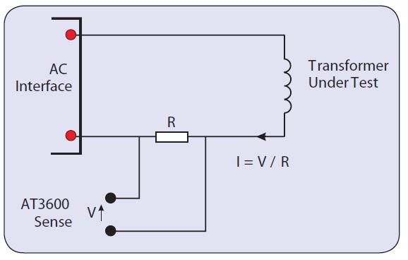
4.2 Basic Principle
Constant-current AC testing uses the normal VOCX test to control the current and make the secondary voltage measurement.
- The current to be controlled, I, is converted to a voltage, V, by means of a current-sensing resistor, R.
- The voltage, V, is connected to the sense terminals of the AT3600, which would normally be used to measure the energizing voltage.
- In the PC Editor, the voltage, V, is used as the energized voltage.
- When VOCX is performed, the AT5600 will trim the source, such that the desired current is provided, I = V / R.
- The transformer secondary voltage is measured in the normal way as the result of the VOCX test.
- The AT adjusts the source voltage to maintain a constant ac current through resistor, R.
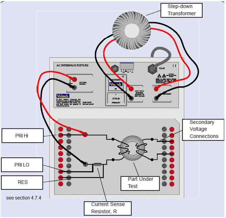
4.3 Connection Diagram
4.4 Current-Sense Resistor
The resistor is used to convert the current flowing the in part into a voltage for the AT3600 to measure.
- The voltage produced (V = I x R) should be in the range 10 mV to 1 V.
- To minimize waveform distortion, the resistor should be less or equal to 1 ohm.
- Check the power consumed (I2R) and choose a suitably rated resistor.
4.5 Step-down Transformer
The step-down transformer is used to increase the current capability of the AT, and to better match the voltage across the part to the characteristics of the AT source.
- Ratio should provide required current with good margin.
- VA rating must be greater than VA required to energize the part and the sense resistor.
- An external ac source may be used to increase the VA rating of the AT3600's generator.
4.6 Worked Example
A laminate core is to be tested in accordance with IEC60404-2.
Under a constant ac current of up to 3 A, 1 V at 50Hz in the primary test winding, the secondary voltage is measured and limits are applied in terms of the rectified mean voltage (RMS scaled).
4.6.1 Resistor
To produce 1 V at 3 A,
R = 1 V / 3 A
R = 0.333 Ohm. Choose 0.5 Ohm standard value.
V = 3 A x 0.5 Ohm
V = 1.5 V
W = I x I x R
W = 4.50 Choose 5 W standard part.
Resistor is 0.5 Ohm, 5 W. Voltage produced will be 1.5 V.
4.6.2 Step-down Transformer
Look for a stock transformer with, say, a 5 A secondary current rating.
A stock transformer will usually have a 110 and/or 230 V primary.
VA rating is that of the part plus the current sense resistor.
VA = 3 A x (1+1.5)V = 7.5 VA
Choose a 7.5 VA (or greater) transformer with a 5 A low-voltage secondary.
Toroidal transformers are ideal, since they will have low losses.
For example:
Primary: 230 V Secondary: 2 x 6 V @ 2.5 A.
The secondaries are connected in parallel to provide a 6 V, 5 A output.
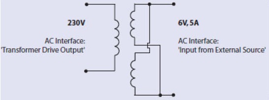
The step-down transformer will supply the part under test and the current-sense resistor in series.
The step-down transformer's secondary voltage, Vs, being:
Vs = 1.5 V +1 V = 2.5 V
The AT must supply 2.5 x 230:6 to the primary of the transformer.
2.5 x 230 / 6 = 95.8 V
The AT can supply 270 V, so 95.8 V is well within its capability.
4.6.3 Programming
It is convenient to use the MAGX test at first, since this will confirm that the desired current is being generated.
4.6.4 Schematic
In the previous connection diagram, the return or 'low' end of the sense resistor has been connected to node 5, and the higher voltage end of the resistor connected to node 3.
For optimum accuracy, it is important that the physical 'low' connection is also designated as the 'low' terminal in the program.

4.6.5 AC INTERFACE Set Up
Next, you must set up the External Source in the Editor.
The source type is 'AT Output Transformer', and you are required to enter the nominal turns ratio of the transformer.
Remember that the AT will trim the output voltage by comparing the desired voltage (from the program) with that measured across the programmed sense terminals.
The ratio is used to establish a target for voltage ramp-up, when the tester starts the test. Using the correct ratio will optimise test speed.
In this case, the ratio is modified because, when the desired 1.5 V is achieved across the resistor, the step-down transformer must also supply the 1 V across the part under test.
For 1.5 V programmed, the step-down transformer delivers 2.5 V.
Ratio = 230:6 x 2.5:1.5
= 63.9:1
That is, for every 1 V programmed, the AT must supply 63.9 V to the primary of the step-down transformer.
4.6.6 MAGX Test
In the MAGX test, simply enter the required voltage, V, across the resistor to program the constant current, I. In this case, enter 1.5 V.
With an AT connected to the PC Editor and the circuit assembled as shown previously, you may now press the 'Measure' button to run a MAGX measurement.
If the current measured is as desired, then all is well. If not, simply adjust the program voltage to suit. If the tester should fail to return a result, check the wiring and settings carefully.
4.6.7 VOCX Test
Now secondary connections may be made for VOCX tests. Note that VOCX has the option to measure RMS voltage or "mean sense RMS scaled" voltage.

For the mean sense option, the tester measures the rectified mean voltage and multiplies that by 1.11.
This option is offered as a means of comparing the measurements with those made by older legacy mean sensing analog meters and calculated parameters that require rectified mean.
5 AC Constant Current Testing Conclusions
The versatile AT transformer tester already provides an unrivalled range of tests for checking the construction and performance of a wide range of coils and transformers.
By following the above guidelines, users can also seamlessly integrate the testing of cores and transformers under constant AC current conditions into the AT environment, providing high-speed PASS / FAIL testing and accurate, detailed test results for analysis.
6 Appendices
Adding Other Tests
To include other tests such as R, simply use extra nodes to connect directly across the windings in the normal way.
You will have to add and extra 'dummy' winding in the schematic and use those terminal names in the program.
Adding extra tests in this way does not interfere with the operation of the constant current drive explained here.
Extending the Constant Current Range
To test very high VA transformers, the drive may be extended by using an external ac source. 500 VA is available from the AT's internal generator.