Triad TY-306P
Worked Example of Suitable Tests
Audio transformers typically operate in the 20 Hz-20 kHz range and provide isolation and impedance matching between different parts of an audio circuit.
Transformers used in such environments are not only subject to safety standards for isolation (eg FCC 68-.304), but also to specific international standards such as FCC 68.310 and IEEE 455 which govern the common mode rejection ratio of transformers used in telephony systems.
Triad TY-306P
The TY-306P is an audio data/voice-coupling transformer manufactured by Triad Magnetics.

TY-306P Schematic
The AT Editor schematic here represents the transformer.
Measurements of Insertion Loss (ILOS) and Longitudinal balance (LBAL) require source resistors and load resistors to be fitted to the transformer to simulate the impedance of the transmission lines, so that it can be tested under “real world” conditions. Measurements of Return Loss (RLOS) also require a load resistor to be present across pins 3-2.
In the shown schematic this is achieved by having an additional test leads for pins 7 and 8.
In our example, “7RES” is a test lead, also connected to pin 7, with a 300-Ohm resistor in series.
However, it connects to a different test node on the AT Tester.
This allows us perform “normal” tests on pin “7”, and then use “7RES” when we wish to test using the load resistor in-situ.
It is important to note that both “7” and “7RES” connect physically to the same pin on the actual transformer.
When “7RES” is not being used, the internal isolation of the relays on the AT Tester nodes will remove “7RES” from having any effect on the other measurements made.
A similar situation occurs on Pin 6 with the associated “6RES”
There is also an additional 600-Ohm resistor fitted across nodes 2 and 3.
This is to provide the load resistor needed for ILOS, RLOS and LBAL.
The fixture also shorts pin 5 to pin 8 to enable the transformer to be tested as a whole entity.

The 6 pins of the transformer are ideally suited for Kelvin pin connections.
As stated before, the pins 5 and 8 are terminated independently on the transformer itself, but the test fixture has a permanent short introduced on these two pins to allow for combined primary testing, whilst still allowing for independent winding testing.

The program first checks the DC resistance of the 3 windings and also one additional check of the DC resistance of the combined primary across pins 7-6 to check correct winding and fixture insertion.
Next the standard TR test checks the whole primary to secondary, then one half of the primary to the other half of the secondary.
We now run a series of Voltech AT tests specifically designed for audio transformers
RLOS (Return Loss) measures the power reflected by the transformer (note that the 600 Ohm Load value is used in the test program)
ILOS (Insertion Loss) measures the power lost inside the transformer (note that the 600 Ohm Load and 600 Ohm Source load values are used in the test program, and nodes 7RES and 6RES are used to enable these resistances)
FREQ (Frequency response) then performs a range of ILOS tests over defined frequencies to check that the dB over frequencies has a flat response
LBAL (Longitudinal balance) then checks the CMRR of the part at the 3 points (200 Hz, 1 Khz and 4 Khz) defined by the part specification.
Finally, the isolation is tested at the nominated 1500 Volts for 1 second.
|
# |
Test |
Description |
Pins and Conditions |
Reason |
| 1 | R | DC resistance | pin 2-3, test for < 200 Ohms | To check the winding resistance is below a maximum. Also acts as a check of correct wire gauge and good termination. |
| 2 | R | DC resistance | pin 7-8, test for <50 Ohms | To check the winding resistance is below a maximum. Also acts as a check of correct wire gauge and good termination. |
| 3 | R | DC resistance | pin 6-5, test for <50 Ohms | To check the winding resistance is below a maximum. Also acts as a check of correct wire gauge and good termination. |
| 4 | R | DC resistance | pin 7-6, test for <100 Ohms | To check the winding resistance is below a maximum. Also acts as a check of correct wire gauge and good termination. |
| 5 | TR | Turns Ratio | Energise pins 6-7,1 V 1 kHz, check Turns ration 6-7:3-2 to be 1.2:1 -+ 2% | To check correct ratio of windings from all of primary to secondary |
| 6 | TR | Turns Ratio | Energise pins 6-5,1 V 1 kHz, check Turns ration 6-5:7-8 to be 1.2:1 -+ 2% | To check correct ratio of windings from P1 to P2 |
| 7 | RLOS | Return Loss | Pin 7-6 , 5V 3 Khz, Real impedance = 600 Ohms (this is the resistor across 2-3), check that RLOS > 10 dB as per spec sheet | This test measures the power reflected by the transformer, compared to the transmitted power. As such, Large RLOS values equate to better power transfer and lower losses. |
| 8 | ILOS | Insertion Loss | Input pins 6RES-7RES (so that the 2 x 300 ohm resistors are used). Output pins 3-2. Source R = 600 Ohms, Load =600 Ohms, test at 5V, 3 kHz. Check ILOS < 1.5 dB | This test measures the power lost inside the transformer. It is expressed as theoretical power over real power, so an ideal transformer will have a low ILOS number |
| 9 | FREQ | Frequency Response | Input pins 6RES-7RES (so that the 2 x 300 ohm resistors are used). Output pins 3-2. 5V 2 KHz as nominal, check to 500 Hz, 1 kHz, 3 kHz, 4 kHz. Limits +/- 0.5 dB as per spec. | This test checks the performance if ILOS over a user-selected range of frequencies compared to one nominated frequency. Results are expressed as the largest deviation from nominal, hence a large result signifies poor frequency response. |
| 10 | LBAL | Longitudinal Balance | Hi ; 6RES-7RES, LO ; 3-2, Common ; CORE . 5V, 200 Hz. Check for > 60 dB, as per spec. | This test checks the common mode performance of the transformer. The 2x 300 Ohm resistors are used to simulate the source line impedance, and the 600 Ohm is still present as the load impedance. A high figure represents good rejection of common mode signals |
| 11 | LBAL | Longitudinal Balance | as above, but at 1 kHz, Check for > 60 dB as per spec. | as above to check performance at 1 kHz |
| 12 | LBAL | Longitudinal Balance | as above, but at 4 kHz, Check for > 45 dB as per spec. | as above to check performance at 4 kHz |
| 13 | HPAC | AC Hi-Pot | 1 kV AC, 1 second, Pins 1&4 High, Pins 2,3 Lo | To check isolation as per datasheet. |
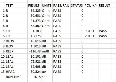
| AT5600 Run time 4.18 sec | ||||
| (AT3600 Run time 10.81 sec) |