Welcome to the DC1000A Quick Start Tutorial
Quick Start Guide if you are new to the DC1000A, or have received a unit to try out
The DC1000A precision DC bias current source features unique patented technology that permits its use with any manufacturer’s LCR meter.
The following page will guide you through the set up and testing of a sample inductor to demonstrate the capabilities of our DC1000A
The following guide gives you a quick tutorial using a sample MURATA inductor that we have provided for you in the box with the DC1000A demo unit.
In this guide we will measure the 47 uH sample inductor at 30 kHz with the LCR, and then vary the DC BIAS current to show it saturates above 7 A DC.
Please note that the nominal inductance tolerance is +/- 15%, so different samples may vary slightly in their 0 A DC inductance from the example results later in this document.
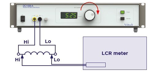
See Right - DC1A performing sweep as Keysight E4980AL measures Ls
DC1000A Quick Start Tutorial
Click each section to expand or collapse.
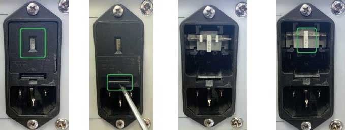
CHECK MAINS INPUT SETTINGS
The DC1000 has a selectable mains input for 100-125 V or 200-250 V Main supply. Please check that this is set correctly for your local supply.
The setting is shown by either 230 or 110 in the filter window.
To change this, first remove the cover using a flat blade screwdriver. Remove the grey terminal block. Refit the terminal block to show 110 V and replace the input cover.
SET-UP - WARM-UP
As with any measuring equipment, allow both the DC1000A and your LCR to warm up to ensure stable readings. Consult your LCR meter user manual for suggested warm-up times.
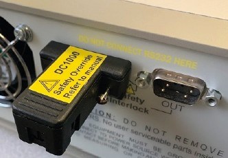
FIT INTERLOCK OVER-RIDE PLUG
Enable the DC1000 by fitting the Interlock Override Plug (in the box) into the Interlock IN port on the rear of the unit (see below)
The DC1000A is designed to supply a range of currents on any transformer or inductor to give you a full solution in one unit.
The DC10000A should always be used with a safety system, such as our own Light Curtain, or alternatively your own interlock system to protect the operator from risk of shock.
This protection is enforced by the DC1000A Interlock Port on the rear of the unit.
If a valid safety device is not connected to this port, then the unit will not generate any dangerous voltages.
For the purposes of evaluation, we have provided an override plug that bypasses this protection.
As such this Interlock Bypass Plug should ONLY be used by qualified personnel.
All personnel should be aware that high currents can be present on the UUT during test execution.
The following steps will walk you through quick manual measurements without compensation. The process for LCR compensation is covered at the end of this page
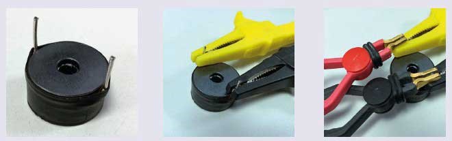
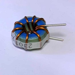
1 Take the sample MURATA 1447385C (47uH Power Inductor) that came in the box
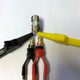
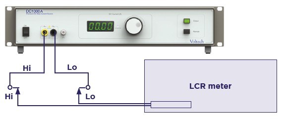
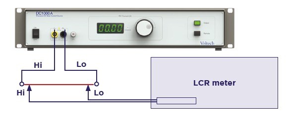
2 Connect to DC1000A clips as shown
3 Connect LCR as shown, taking care to match the HI/LO of the DC1000A connection to the HI/LO connections of your LCR meter
4 Set the LCR to
Measure mode = Ls-Rs
Voltage = 0.1 V
Frequency = 30 kHz
You can now make measurements under load.
1 Select the DC bias current you require using the rotary knob
2 Enable the DC Bias Current by pressing OUTPUT
3 Observe Ls measurements on the LCR
4 Adjustments can be made to the DC bias level while the output is enabled using the rotary knob
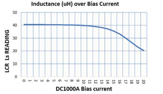
You should see the following inductance readings.
The sample part is rated to 7 A DC, so this confirms its operation up to this point and shows the characteristic fall off as its operating DC is exceed.
0 A DC = 42.3 uH
5 A DC = 42.1 uH
10 A DC = 41.1 uH
15 A DC = 33.5 uH
Remember that the nominal tolerance of the samples is +/- 15%, so different samples may vary slightly in their 0 A DC inductance, but the characteristic roll off of Ls should still be seen.
1 Take the Second sample BOURNS 2301-V-RC (10 uH, 5 mOhm fixed inductor)
2 Connect to DC1000 Croc clips as shown
3 Connect LCR as shown, taking care to match the HI/LO of the DC1000 connection to the HI/LO connections of your LCR meter
4 Set the LCR to
Measure mode = Ls-Rs
Voltage = 40 mV
Frequency = 100 kHz
5 Repeat the above measurement method
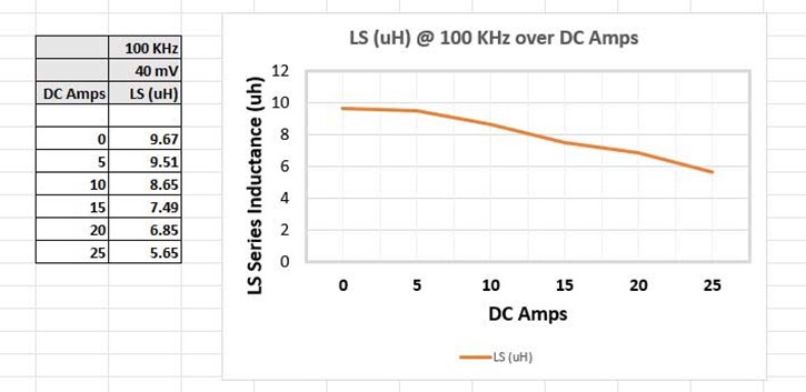
6 You should typically see the following inductance readings.
The sample part is rated to 20 A DC, so this confirms its operation up to this point and shows the characteristic fall off as its operating DC is exceed.
0 A DC = 9.67 uH
5 A DC = 9.51 uH
10 A DC = 8.65 uH
15 A DC = 7.49 uH
20 A DC = 6.85 uH
25 A DC = 5.65 uH
As with any standard LCR reading, you can perform LCR compensation to remove any effects of the LCR leads, and here the DC1000 leads. This may not be needed in all cases, but we have provided the following quick guide to explain this process.
OPEN CIRCUIT COMPENSATION
1 Remove any UUT (unit under test). Set the LCR to 30 kHz / 2 V
2 Try to keep all test leads in the same position as when the UUT is
present
3 Set DC1000 to 0.00 A, using rotary knob if needed
4 Set DC1000 output to ON (press “output” button)
5 Perform open circuit compensation on your LCR meter. For speed of compensation we recommend only compensating at the frequency of measurement.
For example, on the E4980 press MEAS SET UP>CORRECTION.
Set OPEN to ON and SHORT to ON.
Edit SPOT 1 to be 30 kHz.
Then press MEAS OPEN.
6 Set DC1000 output to OFF (press “output” button)
SHORT CIRCUIT COMPENSATION
1 Fit a short between all leads. A bus bar or thick copper wire is ideal for this, as it will give good contact to all four clips. Try to keep all test leads in the same position as when the UUT is present
2 Set the DC1000A to 0.00 A, using rotary knob if needed
3 Set DC1000 output to ON (press “output” button)
4 Perform short circuit compensation on your LCR meter. You should still be on the COMP screen from above. Press MEAS SHORT
5 Set DC1000 output to OFF (press “output” button)
DO NOT disconnect the UUT or LCR while the DC1000 is operating
Always remove the DC bias current by disabling the OUTPUT button before disconnecting either the UUT or the LCR meter.
Always try to keep all leads in the same position to improve the accuracy of the compensation, and hence the accuracy of your measurements
For best performance, especially >100 kHz, connect the earth socket on the front of the DC1000 with the earth socket on the LCR meter
Consult your LCR meter manual for more detailed instructions on LCR compensation and general use.
If your LCR supports ALC (Auto level control) or similar to maintain the requested AC voltage it is recommended to enable this.
This is basically a built in protection on the LCR
If it “sees” more than 2V (or 5V depending on your LCR meter model) across its own terminals it reads "overload" or "0.0".
This voltage will be a combination of :
A) AC volts drop - caused by the LCR V AC settings and the resulting AC drop across the UUT (X=2 x PI x F x L)
And
B) DC volts drop - caused by the DC Amps from the DC 1000 and the resulting V drop caused by the DC resistance on the UUT .
Tips
1) Check for good connections as any poor contacts or underrated test leads can give a small contact resistance that could mean bigger V DC at larger Amps.
2) Check the DC R of your UUT is suitable.
3) Check if reducing the LCR V AC reduces the combined V enough to remove the OVERLOAD
4) Check you have ALC (Level control, or similar) =ON in LCR settings