The Basics Of Transformers
This document explains the basic theory and operation of transformers
1. Introduction to Transformers
Transformer design and test are sometimes viewed as an art rather than a science.
Transformers are imperfect devices, and there will be differences between a transformer's design values, its test measurements, and its real life performance in a circuit.
By going back to basics, this tech note will help design and test engineers understand how a transformer's electrical characteristics are the result of physical properties of the core and windings.
2. Basic Transformer Theory
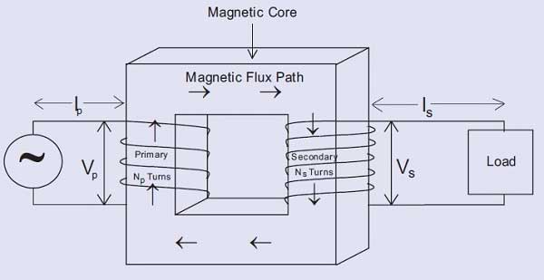
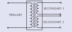
The above figure represents the essential elements for a transformer: a magnetic core with a primary and secondary coil wound on the limbs of the magnetic core.
An alternating voltage (Vp) applied to the primary creates an alternating current (Ip) through the primary.
This current produces an alternating magnetic flux in the magnetic core.
This alternating magnetic flux induces a voltage in each turn of the primary and in each turn of the secondary.
As the flux is a constant, i.e. the same in both primary and secondary:
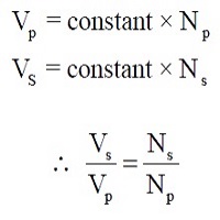
This equation shows that a transformer can be used to step up or step down an ac voltage by controlling the ratio of primary to secondary turns. (Voltage transformer action).
It can also be shown that:
Primary Volt Amperes = Secondary Volt Amperes
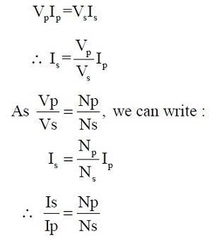
This equation shows that a transformer can be used to step up or step down an ac current by controlling the ratio of primary to secondary turns. (Current transformer action)
It will be noted that there is no electrical connection between the primary and secondary windings.
A transformer, therefore, provides a means of isolating one electrical circuit from another.
These features - voltage/current transformation and isolation - cannot be obtained efficiently by any other means, with the result that transformers are used in almost every piece of electrical and electronic equipment in the world.
3. B-H curves
When the primary of a transformer is energized with the secondary unloaded, a small current flows in the primary. This current creates a 'magnetizing force' that produces the magnetic flux in the transformer core.
The magnetizing force (H) is equal to the product of magnetizing current and the number of turns, and is expressed as Ampere - Turns.
For any given magnetic material, the relationship between magnetizing force and the magnetic flux produced can be plotted. This is known as the B-H curve of the material.
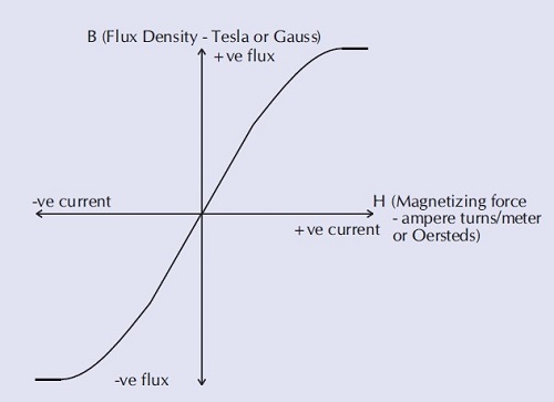
From the B-H curve it can be seen that, as the magnetizing force is increased from zero, the flux increases up to a certain maximum value of flux.
Above this level, further increases in magnetizing force result in no significant increase in flux. The magnetic material is said to be 'saturated'.
A transformer is normally designed to ensure that the magnetic flux density is below the level that would cause saturation.
The flux density can be determined using the following equation:
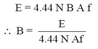
Where:
E represents the RMS value of the applied voltage.
N represents the number of turns of the winding.
B represents the maximum value of the magnetic flux density in the core (Tesla).
A represents the cross-sectional area of the magnetic material in the core (sq. meters).
f represents the frequency of the applied volts.
Note
1 Tesla = 1 Weber/meter²
1 Weber/m² = 10,000 Gauss
1 Ampere-turn per meter = 4 p x 10-3 Oersteds
In practice, all magnetic materials, once magnetized, retain some of their magnetisation even when the magnetizing force is reduced to zero.
This effect is known as 'remanence' and results in the B-H curve for the material exhibiting a response to a decreasing magnetizing force that is different to the response to an increasing magnetizing force.
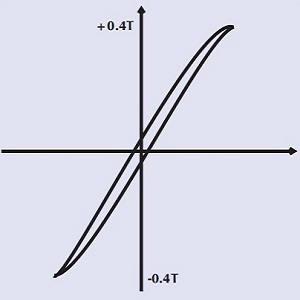
In practice real magnetic materials have a B-H curve as follows:
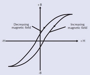
The curve shown above is termed the 'hysteresis' loop of the material, and it represents the true B-H response of the material. (The first B-H curve represented the average or mean of the true B-H loop response).
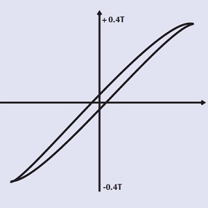
The slope of the B-H curve, the saturation level, and the size of the hysteresis loop are dependent on the type of material used, and on other factors.
This is illustrated using the following examples:
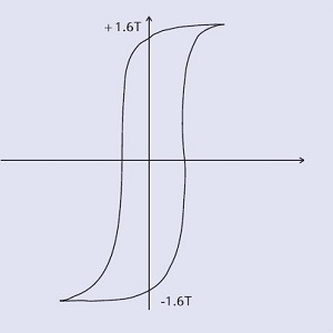 |
Low-grade iron core High-saturation flux density Large loop = large hysteresis loss Suitable for 50/60Hz |
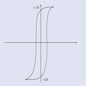 |
High-grade iron core High-saturation flux density Medium loop = medium hysteresis loss Suitable for 400 Hz transformers |
 |
Ferrite core - no air gap Medium-saturation flux density Small loop = small hysteresis loss Suitable for-high frequency transformers |
 |
Ferrite core - large air gap Small loop = small hysteresis loss Suitable for high-frequency Inductors with large DC current |
4. Hysteresis Loss
Hysteresis loss is the result of cycling the magnetic material along its B-H curve.
It represents the energy taken as the applied voltage, aligns magnetic dipoles first in one direction, and then in the other.
The loss increases with the area of the B-H curve enclosed. As the material is driven closer to saturation, both the area within the curve, and the corresponding energy loss each cycle, increase substantially.
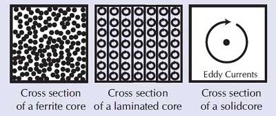
5. Eddy Current Loss
Eddy current loss is caused by small currents circulating within the core material, stimulated by the alternating flux in the core.
The I*I*R power loss ("heating" loss) associated with these currents produces heating of the core known as eddy current loss.
In iron-cored transformers, insulated iron sheets known as laminations are used to minimize this effect by restricting the path for circulating currents.
Ferrite cores restrict these paths even further.
6. Transformer Equivalent Circuit
An ideal transformer with one primary winding and two secondary windings can be represented as shown below
Such a transformer has the following characteristics:
• No losses
• Perfect coupling between all windings
• Infinite open circuit impedance (i.e., no input current when secondaries are open-circuited).
• Infinite insulation between windings
In reality, practical transformers show characteristics that differ from those of an ideal transformer.
Many of these characteristics can be represented by a transformer equivalent circuit:
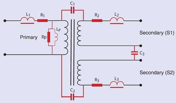
Where:
R1, R2, R3 represent the resistance of the winding wire.
C1, C2, C3 represent the capacitance between the windings.
Rp represents the losses which are due to the eddy current and hysteresis losses. These are the real power losses, sometimes called the core loss, that may be measured by performing an open-circuit power measurement. Because there is no load current, there is very little I2R copper loss in the energized winding, and the watts measured at no load are nearly all due to the core.
Lp represents the impedance due to the magnetizing current. This is the current that generates the magnetizing force, H, used in the B-H loop diagrams. Note that this current may not be a simple sine wave, but can have a distorted, peaked shape, if the transformer is operated in the non-linear region of the B-H curve. This is usually the case for line-frequency, laminate type transformers.
L1, L2, L3 represent the leakage inductance of each of the windings. (This is discussed in detail in Voltech Note 104-105, "Leakage Inductance".)
7. Conclusions
The equivalent circuit of a transformer reflects the real properties of the magnetic circuit comprising the core and windings.
The equivalent circuit can therefore be used with confidence to understand and predict the transformer's electrical performance in a variety of situations.
8. Further Reading
The equivalent circuit can also be used to help understand and optimise the tests and test conditions that can be used to check that a transformer has been constructed correctly.
Further technical notes in this series discuss how the equivalent circuit parameters are used to derive practical tests for transformers to guarantee their quality in a manufacturing environment.